


FCD-1X modem/telephone/ISDN Settings and Configuration
RAD DATA COMMUNICATIONS
FCD-1X
Card Type | T1 CSU/DSU |
Chip Set | Unidentified |
I/O Options | AC power connector, V.35 DTE port (34-pin connector), 9-pin serial port (RS-232), 25-pin serial port (RS-530), T1 network interface via 15-pin connector |
Wiring Type | 100ohm shielded twisted pair via 15-pin connector |
T1 Transfer Rate | 1.544Mbps |
T1 Protocol | AMI, B8ZS, B7ZS |
Frame type | D4,ESF |
Data Bus | External |
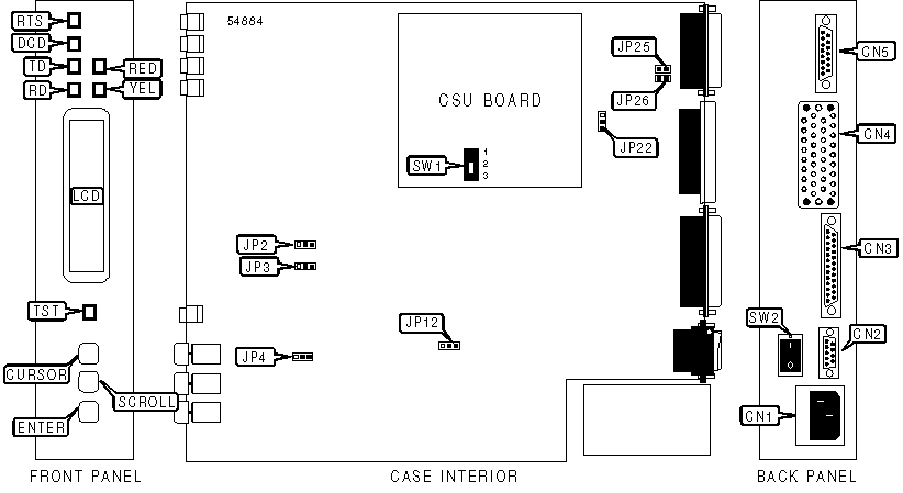
CONNECTIONS | |||
Function | Label | Function | Label |
AC power connector | CN1 | DCE/DTE port (34-pin connector) | CN4 |
9-pin serial port | CN2 | Network interface via 15-pin connector | CN5 |
DCE/DTE port (25-pin connector) | CN3 | Power switch | SW2 |
USER CONFIGURABLE SETTINGS | |||
Setting | Label | Position | |
| » | Debug self test mode disabled | JP2 | Pins 1 & 2 closed |
Debug self test mode enabled | JP2 | Pins 2 & 3 closed | |
| » | Default password enabled. Password=FCD-1/X | JP3 | Pins 2 & 3 closed |
User password enabled | JP3 | Pins 1 & 2 closed | |
| » | Watchdog timer enabled | JP4 | Pins 1 & 2 closed |
Watchdog timer disabled | JP4 | Pins 2 & 3 closed | |
| » | Signal ground is connected to the frame ground | JP12 | Pins 2 & 3 closed |
Signal ground is not connected to the frame ground | JP12 | Pins 1 & 2 closed | |
| » | Internal -5V enabled | JP22 | Pins 1 & 2 closed |
Grounded to pin 15 in the main link connector (CN5) | JP22 | Pins 2 & 3 closed | |
| » | Allows connection of the line controlled by JP22 to pin 15 of main link connector (CN5) for powering external device | JP25 | Closed |
Does not allow connection of the line controlled by JP22 to pin 15 of main link connector (CN5) for powering external device | JP25 | Open | |
| » | Allows connection of internal +5V, via resistor, to pin 14 of main link connector (CN5) for powering external device | JP26 | Closed |
Does not allow connection of internal +5V, via resistor, to pin 14 of main link connector (CN5) for powering external device | JP26 | Open | |
T1 TRANSMIT LEVEL SELECTION | |||
Net build | Label | Position | |
| » | 0dB | SW1 | 1 |
7.5dB | SW1 | 2 | |
15dB | SW1 | 3 | |
DIAGNOSTIC LED(S) | |||
LED | Color | Status | Condition |
RTS | Unidentified | On | RTS signal is high |
RTS | Unidentified | Off | RTS signal is low |
DCD | Unidentified | On | DCD signal is high |
DCD | Unidentified | Off | DCD signal is low |
TD | Unidentified | On | CSU/DSU is detecting pulses from the local DTE |
TD | Unidentified | Off | CSU/DSU is not detecting pulses from the local DTE |
RD | Unidentified | On | CSU/DSU is receiving pulses from network |
RD | Unidentified | Off | CSU/DSU is not receiving pulses from network |
RED | Unidentified | On | CSU/DSU is detecting a red alarm condition |
RED | Unidentified | Off | CSU/DSU is not detecting a red alarm condition |
YEL | Unidentified | On | CSU/DSU is detecting a yellow alarm condition |
YEL | Unidentified | Off | CSU/DSU is not detecting a yellow alarm condition on |
TST | Unidentified | On | CSU/DSU loopback test active |
TST | Unidentified | Off | CSU/DSU loopback test not running |


My Books

