


FCD-1L modem/telephone/ISDN Settings and Configuration
RAD DATA COMMUNICATIONS
FCD-1L
Card Type | T1 CSU/DSU |
Chip Set | Unidentified |
I/O Options | AC power connector, 25-pin connector (RS-530), T1 network interface via RJ-48 connector |
Wiring Type | RJ-48 120ohm shielded twisted pair |
T1 Transfer Rate | 1536Kbps (supports multiples of 56Kbps or 64Kbps) |
T1 Protocol | AMI, B8ZS, B7ZS |
Frame Type | ESF, D4SF |
Data Bus | External |
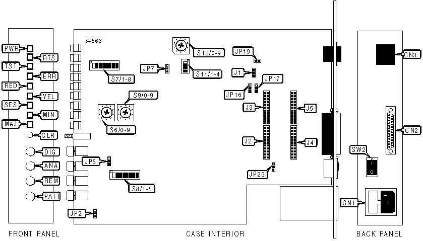
CONNECTIONS | |||
Function | Label | Function | Label |
Analog loopback activation push-button | ANA | Digital loopback activation push-button | DIG |
Alarm clear push-button | CLR | Maintenance connector | J1 |
AC power connector | CN1 | Test pattern activation push-button | PATT |
DTE/DCE serial port (25-pin connector) | CN2 | Remote digital loopback activation push-button | REM |
Network interface via RJ-48 connector | CN3 | Power switch | SW2 |
Note: FCD-1L also available with DC power connector | |||
USER CONFIGURABLE SETTINGS | |||
Setting | Label | Position | |
| » | Front panel switches enabled | JP2 | Pins 1 & 2 closed |
Front panel switches disabled | JP2 | Pins 2 & 3 closed | |
| » | Watchdog enabled | JP5 | Pins 1 & 2 closed |
Watchdog disabled | JP5 | Pins 2 & 3 closed | |
| » | Debug self test mode disabled | JP7 | Pins 2 & 3 closed |
Debug self test mode enabled | JP7 | Pins 1 & 2 closed | |
| » | Phantom power feeding is disabled | JP19 | Open |
Phantom power feeding is enabled | JP19 | Closed | |
| » | Signal ground is connected to the frame ground | JP23 | Pins 2 & 3 closed |
Signal ground is not connected to the frame ground | JP23 | Pins 1 & 2 closed | |
| » | CTS forced high | S7/3 | On |
CTS follows remote RTS | S7/3 | Off | |
| » | Fast synchronization timing (1 sec) | S7/4 | Off |
AT&T TR-62411 synchronization timing (10 sec) | S7/4 | On | |
| » | Multiframe ESF mode enabled | S7/5 | Off |
Multiframe D4 (SF) mode enabled | S7/5 | On | |
| » | Factory configured - do not alter | S7/8 | Unidentified |
| » | Nx64 mode | S11/1 | Off |
Nx56 mode | S11/1 | On | |
| » | Loopback timing mode enabled | S11/2 | On |
Internal clock mode enabled | S11/2 | Off | |
| » | Time slot allocation is sequential, starting from slot 1 | S11/3 | On |
Data is inserted in alternate time slots, starting from slot 1 | S11/3 | Off | |
| » | Factory configured - do not alter | S11/4 | Unidentified |
BAUD RATE | ||
Setting | S6 | S9 |
Unframed | 0 | 0 |
Operational baud rate set to 1x64 | 0 | 1 |
Operational baud rate set to 2x64 | 0 | 2 |
Operational baud rate set to 3x64 | 0 | 3 |
Operational baud rate set to 4x64 | 0 | 4 |
Operational baud rate set to 20x64 | 2 | 0 |
Operational baud rate set to 21x64 | 2 | 1 |
Operational baud rate set to 22x64 | 2 | 2 |
Operational baud rate set to 23x64 | 2 | 3 |
Operational baud rate set to 24x64 | 2 | 4 |
Note: Multiples of 56Kbps or 64Kbps, up to 24 may be selected, for a maximum of 1344Kbps for multiples of 56Kbps or a maximum of 1536Kbps for multiples of 64Kbps. 25-99 are not used. | ||
DTE INTERFACE | ||||
Function | J2 | J3 | J4 | J5 |
V.35 DTE interface | Open | Open | Board connected | Board connected |
RS-422 interface | Board connected | Board connected | Open | Open |
IDLE CODE | |||||||||
Setting | S8/1 | S8/2 | S8/3 | S8/4 | S8/5 | S8/6 | S8/7 | S8/8 | |
| » | Default idle code | Off | Off | Off | Off | Off | Off | Off | Off |
Note: On=0, Off=1. Switch S8/1 is the most significant bit. Switch S8/2 is the least significant bit. Values are currently unidentified. | |||||||||
LOOP ACTIVATION | |||
Setting | JP16 | JP17 | |
| » | Loop activation enabled | Pins 2 & 3 closed | Pins 2 & 3 closed |
Loop activation disabled | Pins 1 & 2 closed | Pins 1 & 2 closed | |
PORT TIMING | |||
Setting | S7/1 | S7/2 | |
DTE1 port timing | On | On | |
| » | DCE port timing | On | Off |
DTE2 port timing | Off | On | |
SOUND CONFIGURATION | ||
Net build | S12 | |
| » | 0dBm | 0 |
-7.5dBm | 1 | |
-15dBm | 2 | |
-22.5dBm | 3 | |
ZERO SUPPRESSION MODE | |||
Setting | S7/6 | S7/7 | |
Transparent suppression | On | On | |
B7ZS | On | Off | |
| » | B78S | Off | On |
DIAGNOSTIC LED(S) | |||
LED | Color | Status | Condition |
PWR | Unidentified | On | Power is on |
PWR | Unidentified | Off | Power is off |
RTS | Unidentified | On | RTS input line is on |
RTS | Unidentified | Off | RTS input line is off |
TST | Unidentified | On | Device is conducting a test |
TST | Unidentified | Off | Device is not conducting a test |
ERR | Unidentified | On | Error detected in the test pattern |
ERR | Unidentified | Off | Error not detected in the test pattern |
RED | Unidentified | On | Red alarm condition detected by local FCD-1L |
RED | Unidentified | Off | Red alarm condition not detected by local FCD-1L |
YEL | Unidentified | On | Yellow alarm condition detected by remote FCD-1L |
YEL | Unidentified | Off | Yellow alarm condition not detected by remote FCD-1L |
SES | Unidentified | On | Severe error second detected |
SES | Unidentified | Off | Severe error second not detected |
MIN | Unidentified | On | Minor alarm condition detected. Remains lit until fault condition disappears, or CLR button is pushed |
MIN | Unidentified | Off | Minor alarm condition not detected |
MAJ | Unidentified | On | Major alarm condition detected. Remains lit until fault condition disappears, or CLR button is pushed |
MAJ | Unidentified | Off | Major alarm condition not detected |


My Books

