


652 modem/telephone/ISDN Settings and Configuration
MOTOROLA, INC.
652
Card Type | ISDN TA/X.25 PAD |
Processor | Motorola 68302 |
Processor Speer | Unidentified |
Chip Set | Unidentified |
Maximum Onboard Memory | 1MB DRAM/1.25MB Flash RAM |
Transfer Rate | 64Kbps x 2 |
Data Bus | External |
ISDN Protocol | Unidentified |
Switch Type | Unidentified |
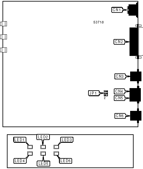
CONNECTIONS | |||
Function | Label | Function | Label |
DC power in | CN1 | Analog adapter 1 | CN4 |
Serial port | CN2 | Analog adapter 2 | CN5 |
Serial port | CN3 | ISDN interface | CN6 |
USER CONFIGURABLE SETTINGS | |||
Setting | Label | Position | |
| » | TA is configured for 4-wire line | JP1 | Pins 1 through 4 closed |
TA is configured for 2-wire line | JP1 | Pins 3 through 6 closed | |
Note:JP1 is supplied with a 4-pin shunt. All four pins indicated should be closed with this shunt. | |||
DIAGNOSTIC LED(S) | |||
LED | Color | Status | Condition |
LED1 | Green | On | Software is running |
LED1 | Green | Blinking | Software is running |
LED1 | Green | Off | Software is not running |
LED2 | Red | Blinking | Diagnostic test is running |
LED2 | Red | Off | Diagnostic test is not running |
LED3 | Green | On | TA is receiving power from CN1 |
LED3 | Green | Blinking | TA is receiving power from internal battery |
LED3 | Green | Off | Power is off |
LED4 | Yellow | On | ISDN is connected |
LED4 | Yellow | Off | ISDN is not connected |
LED5 | Yellow | On | Analog adapter 1 is connected |
LED5 | Yellow | Blinking | Analog adapter 1 is off hook |
LED5 | Yellow | Off | Analog adapter 1 is not connected |
LED6 | Yellow | On | Analog adapter 2 is connected |
LED6 | Yellow | Blinking | Analog adapter 2 is off hook |
LED6 | Yellow | Off | Analog adapter 2 is not connected |


My Books

