


SYNC/570I IO card Settings and Configuration
ARNET CORPORATION
SYNC/570I
Card Type | Serial |
Chip Set | Hitachi |
Maximum Onboard Memory | 128KB RAM |
I/O Options | Serial ports (4) |
Data Bus | 16-bit ISA |
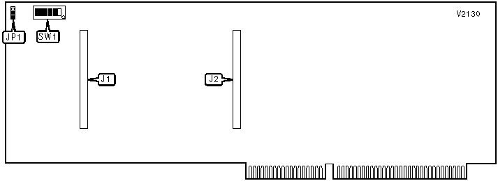
CONNECTIONS | |||
Function | Label | Function | Label |
Four-port daughterboard header | J1 | Two-port daughterboard header | J2 |
USER CONFIGURABLE SETTINGS | |||
Setting | Label | Position | |
| » | Fast Select enabled | JP1 | Pins 2 & 3 closed |
Fast Select disabled | JP1 | Pins 1 & 2 closed | |
BASE I/O ADDRESS | |||||||
Setting | SW1/1 | SW1/2 | SW1/3 | SW1/4 | SW1/5 | SW1/6 | |
000h | On | On | On | On | On | On | |
010h | Off | On | On | On | On | On | |
020h | On | Off | On | On | On | On | |
030h | Off | Off | On | On | On | On | |
040h | On | On | Off | On | On | On | |
| » | 300h | On | On | On | On | Off | Off |
3B0h | Off | Off | On | Off | Off | Off | |
3C0h | On | On | Off | Off | Off | Off | |
3D0h | Off | On | Off | Off | Off | Off | |
3E0h | On | Off | Off | Off | Off | Off | |
3F0h | Off | Off | Off | Off | Off | Off | |
Note: A total of 127 memory address settings are available. The switches are a binary representation of the hexadecimal memory addresses. SW1/7 is the Most Significant Bit and switch SW1/1 is the Least Significant Bit. The switches have the following hexadecimal values: SW1/6=200h, SW1/5=100h, SW1/4=80h, SW1/3=40h, SW1/2=20h, SW1/1=10h. Turn off the switches and add the values of the switches that are off to obtain the correct memory address. (Off=1, On=0) | |||||||
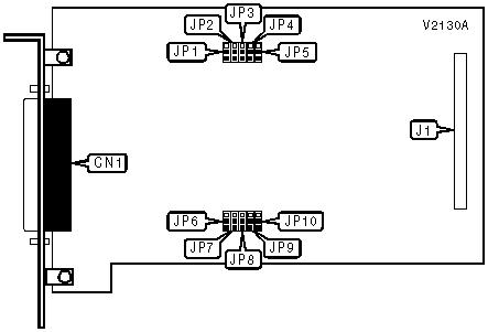
CONNECTIONS | |||
Function | Label | Function | Label |
V.35 or V.24 serial ports via DB-37 | CN1 | Daughterboard header | J1 |
Note: Serial ports are provided via included adapter cable. | |||
PORT 1 TYPE | |||||
Setting | JP1 | JP2 | JP3 | JP4 | JP5 |
V.35 | 1 & 2 | 1 & 2 | 1 & 2 | 1 & 2 | 1 & 2 |
V.24 | 2 & 3 | 2 & 3 | 2 & 3 | 2 & 3 | 2 & 3 |
Note: Pins designated are in the closed position. | |||||
PORT 2 TYPE | |||||
Setting | JP6 | JP7 | JP8 | JP9 | JP10 |
V.35 | 1 & 2 | 1 & 2 | 1 & 2 | 1 & 2 | 1 & 2 |
V.24 | 2 & 3 | 2 & 3 | 2 & 3 | 2 & 3 | 2 & 3 |
Note: Pins designated are in the closed position. | |||||
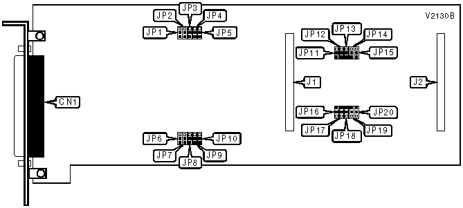
CONNECTIONS | |||
Function | Label | Function | Label |
V.35 or V.24 serial ports via DB-62 | CN1 | Daughterboard header | J2 |
Daughterboard header | J1 | ||
Note: Serial ports are provided via included adapter cable. | |||
PORT 1 TYPE | |||||
Setting | JP1 | JP2 | JP3 | JP4 | JP5 |
V.35 | 1 & 2 | 1 & 2 | 1 & 2 | 1 & 2 | 1 & 2 |
V.24 | 2 & 3 | 2 & 3 | 2 & 3 | 2 & 3 | 2 & 3 |
Note: Pins designated are in the closed position. | |||||
PORT 2 TYPE | |||||
Setting | JP6 | JP7 | JP8 | JP9 | JP10 |
V.35 | 1 & 2 | 1 & 2 | 1 & 2 | 1 & 2 | 1 & 2 |
V.24 | 2 & 3 | 2 & 3 | 2 & 3 | 2 & 3 | 2 & 3 |
Note: Pins designated are in the closed position. | |||||
PORT 3 TYPE | |||||
Setting | JP11 | JP12 | JP13 | JP14 | JP15 |
V.35 | 1 & 2 | 1 & 2 | 1 & 2 | 1 & 2 | 1 & 2 |
V.24 | 2 & 3 | 2 & 3 | 2 & 3 | 2 & 3 | 2 & 3 |
Note: Pins designated are in the closed position. | |||||
PORT 4 TYPE | |||||
Setting | JP16 | JP17 | JP18 | JP19 | JP20 |
V.35 | 1 & 2 | 1 & 2 | 1 & 2 | 1 & 2 | 1 & 2 |
V.24 | 2 & 3 | 2 & 3 | 2 & 3 | 2 & 3 | 2 & 3 |
Note: Pins designated are in the closed position. | |||||
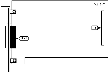
CONNECTIONS | |||
Function | Label | Function | Label |
X.21 serial ports via DB-44 | CN1 | Daughterboard header | J1 |
Note: Serial ports are provided via included adapter cable. | |||


My Books

