


NI5210/8-UTP, NI5210/16-UTP Network Card Settings and Configuration
RACAL INTERLAN, INC.
NI5210/8-UTP, NI5210/16-UTP
NIC Type | Ethernet |
Transfer Rate | 10Mbps |
Data Bus | 8-bit ISA |
Topology | Star |
Wiring Type | Unshielded twisted pair AUI tranceiver via DB-15 |
Boot ROM | Available |
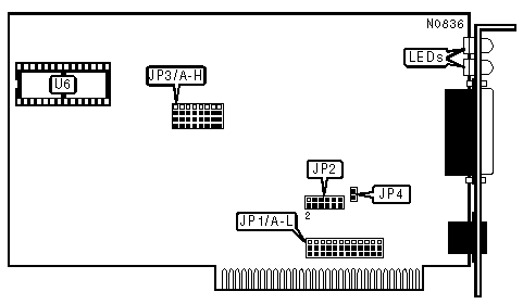
CABLE TYPE | |
Type | JP3/A-H |
Unshielded twisted pair | Pins 1, 2, & 3 closed |
AUI transceiver via DB-15 port | Pins 2, 3, & 4 closed |
BOOT ROM ADDRESS | |||||
Address | JP1/G | JP1/H | JP1/I | JP1/J | |
C0000h | Pins 1 & 2 closed | Pins 1 & 2 closed | Pins 1 & 2 closed | Pins 1 & 2 closed | |
C4000h | Pins 1 & 2 closed | Pins 1 & 2 closed | Pins 1 & 2 closed | Pins 2 & 3 closed | |
| » | C8000h | Pins 1 & 2 closed | Pins 1 & 2 closed | Pins 2 & 3 closed | Pins 1 & 2 closed |
CC000h | Pins 1 & 2 closed | Pins 1 & 2 closed | Pins 2 & 3 closed | Pins 2 & 3 closed | |
D0000h | Pins 1 & 2 closed | Pins 2 & 3 closed | Pins 1 & 2 closed | Pins 1 & 2 closed | |
D4000h | Pins 1 & 2 closed | Pins 2 & 3 closed | Pins 1 & 2 closed | Pins 2 & 3 closed | |
D8000h | Pins 1 & 2 closed | Pins 2 & 3 closed | Pins 2 & 3 closed | Pins 1 & 2 closed | |
DC000h | Pins 1 & 2 closed | Pins 2 & 3 closed | Pins 2 & 3 closed | Pins 2 & 3 closed | |
E0000h | Pins 2 & 3 closed | Pins 1 & 2 closed | Pins 1 & 2 closed | Pins 1 & 2 closed | |
E4000h | Pins 2 & 3 closed | Pins 1 & 2 closed | Pins 1 & 2 closed | Pins 2 & 3 closed | |
E8000h | Pins 2 & 3 closed | Pins 1 & 2 closed | Pins 2 & 3 closed | Pins 1 & 2 closed | |
EC000h | Pins 2 & 3 closed | Pins 1 & 2 closed | Pins 2 & 3 closed | Pins 2 & 3 closed | |
BASE I/O ADDRESS | ||||||
Address | JP1/A | JP1/B | JP1/C | JP1/D | JP1/E | JP1/F |
200h | Pins 1 & 2 | Pins 1 & 2 | Pins 1 & 2 | Pins 1 & 2 | Pins 1 & 2 | Pins 1 & 2 |
208h | Pins 1 & 2 | Pins 1 & 2 | Pins 1 & 2 | Pins 1 & 2 | Pins 1 & 2 | Pins 2 & 3 |
210h | Pins 1 & 2 | Pins 1 & 2 | Pins 1 & 2 | Pins 1 & 2 | Pins 2 & 3 | Pins 1 & 2 |
218h | Pins 1 & 2 | Pins 1 & 2 | Pins 1 & 2 | Pins 1 & 2 | Pins 2 & 3 | Pins 2 & 3 |
220h | Pins 1 & 2 | Pins 1 & 2 | Pins 1 & 2 | Pins 2 & 3 | Pins 1 & 2 | Pins 1 & 2 |
3D8h | Pins 2 & 3 | Pins 2 & 3 | Pins 2 & 3 | Pins 1 & 2 | Pins 2 & 3 | Pins 2 & 3 |
3E0h | Pins 2 & 3 | Pins 2 & 3 | Pins 2 & 3 | Pins 2 & 3 | Pins 1 & 2 | Pins 1 & 2 |
3E8h | Pins 2 & 3 | Pins 2 & 3 | Pins 2 & 3 | Pins 2 & 3 | Pins 1 & 2 | Pins 2 & 3 |
3F0h | Pins 2 & 3 | Pins 2 & 3 | Pins 2 & 3 | Pins 2 & 3 | Pins 2 & 3 | Pins 1 & 2 |
3F8h | Pins 2 & 3 | Pins 2 & 3 | Pins 2 & 3 | Pins 2 & 3 | Pins 2 & 3 | Pins 2 & 3 |
Notes:Pins designated should be in the closed position. A total of 64 base I/O addresses are available. The jumpers are a binary representation of the decimal memory addresses. Jumper JP1/F is the Least Significant Bit and JP1/A is the Most Significant Bit. The jumpers have the following decimal values: JP1/F=8, JP1/E=16, JP1/D=32, JP1/C=64, JP1/B=128, JP1/A=256. Configure the jumpers and add 512 and the values of the jumpers closing pins 2 & 3 to obtain the correct memory base I/O address. | ||||||
INTERRUPT SETTINGS | |
IRQ | JP2 |
2 | Pins 1 & 2 closed |
3 | Pins 3 & 4 closed |
4 | Pins 5 & 6 closed |
5 | Pins 7 & 8 closed |
6 | Pins 9 & 10 closed |
7 | Pins 11 & 12 closed |
IBM PC/XT COMPATIBILITY | |
Setting | JP4 |
NIC installed in main board slot 8 | Closed |
NIC installed in main board slot 1-7 | Open |
Note:This jumper only applies when the NIC is installed in an IBM PC/XT. | |
ONBOARD RAM/BOOT ROM CONFIGURATION | ||
Function | JP1/K | JP1/L |
8KB of RAM installed (NI5120-UTP-8) | Pins 2 & 3 closed | N/A |
16KB of RAM installed (NI5120-UTP-16) | Pins 1 & 2 closed | Pins 1 & 2 closed |
8KB of RAM and Boot ROM installed | Pins 1 & 2 closed | Pins 2 & 3 closed |
Note: Socket U6 can either be an 8K RAM chip or a Boot ROM. | ||
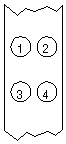
DIAGNOSTIC LEDS | |||
LED | Color | Status | Condition |
LED1 | Red | Off | Data is not being received |
LED1 | Red | On | Data is being received |
LED2 | Yellow | Off | Data is not being transmitted |
LED2 | Yellow | On | Data is being transmitted |
LED3 | Green | Off | UTP link status OK |
LED3 | Green | On | UTP link broken |
LED4 | Red | Off | AUI port selected |
LED4 | Red | On | UTP port selected |
Note: LED3 is only active when the UTP port is selected. | |||


My Books

