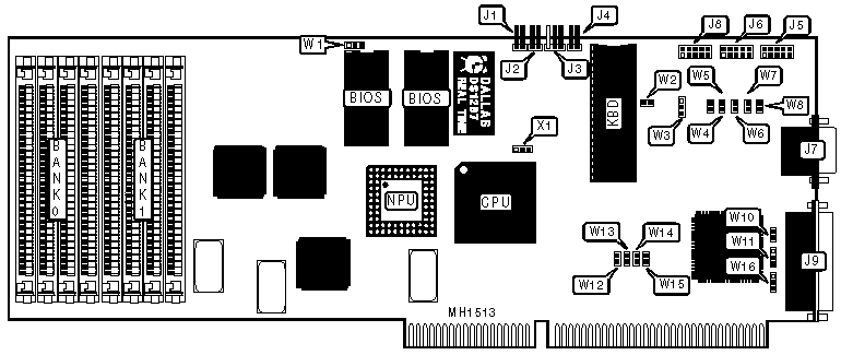
QPC-5142 Motherboard Settings and Configuration
QUALOGY, INC.
QPC-5142
Processor | 80386DX |
Processor Speed | 16/20MHz |
Chip Set | G2 |
Max. Onboard DRAM | 8MB |
Cache | None |
BIOS | AMI |
Dimensions | 330mm x 120mm |
I/O Options | Parallel port, serial ports (2-RS232, 1-RS422) |
NPU Options | 80387DX |
CONNECTIONS | |||
Purpose | Location | Purpose | Location |
Reset switch | J1 | Serial port B (RS232) | J6 |
Speaker | J2 | Serial port A (RS232) | J7 |
Keylock | J3 | Keyboard | J8 |
Turbo LED | J4 | Parallel port | J9 |
Serial port B (RS422) | J5 |
|
|
USER CONFIGURABLE SETTINGS | |||
Function | Jumper | Position | |
» | BIOS type select 27256 | W1 | pins 1 & 2 closed |
| BIOS type select 27512 | W1 | pins 2 & 3 closed |
» | Monitor type select color | W2 | Closed |
| Monitor type select monochrome | W2 | Open |
» | RS232 12V from backplane | W3 | pins 2 & 3 closed |
| RS232 12V from card | W3 | pins 1 & 2 closed |
» | Factory configured - do not alter | X1 | Unknown |
DRAM CONFIGURATION | ||
Size | Bank 0 | Bank 1 |
1MB | (4) 256K x 9 | NONE |
2MB | (4) 256K x 9 | (4) 256K x 9 |
4MB | (4) 1M x 9 | NONE |
8MB | (4) 1M x 9 | (4) 1M x9 |
SERIAL PORT CONFIGURATION | ||||||||
RS422 (J5) | RS232 (J6) | RS232 (J7) | W8 | W11 | W12 | W13 | W15 | W16 |
Disabled | COM2 | COM1 | Closed | pins 1&2 | Closed | Closed | Closed | pins 1&2 |
COM2 | Disabled | COM1 | Open | pins 2&3 | Closed | Closed | Closed | pins 1&2 |
Disabled | COM1 | COM2 | Closed | pins 1&2 | Open | Closed | Closed | pins 2&3 |
COM1 | Disabled | COM2 | Open | pins 1&2 | Open | Closed | Closed | pins 2&3 |
Disabled | COM2 | Disabled | Closed | pins 1&2 | Closed | Closed | Open | pins 1&2 |
COM2 | Disabled | Disabled | Open | pins 2&3 | Closed | Closed | Open | pins 1&2 |
Disabled | COM1 | Disabled | Closed | pins 1&2 | Open | Closed | Open | pins 2&3 |
COM1 | Disabled | Disabled | Open | pins 1&2 | Open | Closed | Open | pins 2&3 |
Disabled | Disabled | COM1 | N/A | pins 1&2 | Open | Open | Closed | pins 1&2 |
Disabled | Disabled | COM2 | N/A | pins 2&3 | Open | Open | Closed | pins 2&3 |
Disabled | Disabled | Disabled | N/A | N/A | N/A | Open | Open | N/A |
Note: Serial port B is configurable as either a RS422 port using J5 or a RS232 port using J6, but both connectors (J5 & J6) cannot be active at the same time. Pins designated should be in the closed position. | ||||||||
SERIAL PORT B (J5/RS422) DRIVER ENABLE CONFIGURATION | |||
Function | Jumper | Position | |
» | DTR signal reflects true state of device | W4 | Open |
| DTR signal is forced true | W4 | Closed |
» | RTS signal reflects true state of device | W5 | Open |
| RTS signal is forced true | W5 | Closed |
» | CTS signal reflects true state of device | W6 | Open |
| CTS signal is forced true | W6 | Closed |
» | All of the above signals reflect true state of device | W7 | Open |
| All of the above signals are forced true | W7 | Closed |
Note:The above jumpers are mutually exclusive and only one of them should be closed at a time. | |||
PARALLEL PORT CONFIGURATION | |||||
Port | Address | IRQ | W10 | W14 | |
» | LPT1 | 378-37Fh | IRQ7 | Closed | Closed |
| Disabled | N/A | Disabled | Open | Open |
My Books

