QPC-5132 Motherboard Settings and Configuration
QUALOGY, INC.
QPC-5132
Processor | 80286 |
Processor Speed | 8/10/12.5/16MHz |
Chip Set | G2 |
Max. Onboard DRAM | 4MB |
SRAM Cache | NONE |
BIOS | AMI |
Dimensions | 330mm x 120mm |
I/O Options | Parallel port, serial ports (2-RS232, 1-RS422) |
NPU Options | 80287 |
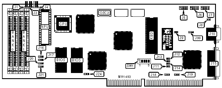
CONNECTIONS | |||
Purpose | Location | Purpose | Location |
Reset switch | J1 | Serial port B (RS422) | J6 |
Speaker | J3 | Serial port B (RS232) | J7 |
Keylock | J4 | Serial port A (RS232) | J10 |
Keyboard | J5 | Parallel port | J15 |
USER CONFIGURABLE SETTINGS | |||
Function | Jumper/Switch | ||
| » | Monitor type select color | J9 | Open |
Monitor type select monochrome | J9 | Closed | |
| » | Parallel port enabled | J12 | Closed |
Parallel port disabled | J12 | Open | |
| » | BIOS type select 27256 | J24 | pins 1 & 2 closed |
BIOS type select 27512 | J24 | pins 2 & 3 closed | |
| » | RS232 12V from backplane | J99 | pins 2 & 3 closed |
RS232 12V from card | J99 | pins 1 & 2 closed | |
| » | Bus speed select slow | SW1/switch 2 | Off |
Bus speed select fast | SW1/switch 2 | On | |
| » | CPU speed select OSC3 | SW1/switch 5 | Off |
CPU speed select OSC3 | SW1/switch 5 | On | |
DRAM CONFIGURATION | |||||
Size | Bank 0 | Bank 1 | SW1/switch 1 | SW1/switch 3 | SW1/switch 4 |
512KB | (2) 256K x 9 | NONE | On | On | Off |
1MB | (2) 256K x 9 | (2) 256K x 9 | Off | On | Off |
2MB | (2) 1M x 9 | NONE | Off | Off | On |
4MB | (2) 1M x 9 | (2) 1M x 9 | Off | Off | Off |
SERIAL PORT CONFIGURATION | ||||||||
RS422 (J6) | RS232 (J7) | RS232 (J10) | J8 | J11 | J13 | J14 | J18 | J19 |
Disabled | COM2 | COM1 | Closed | Closed | Closed | Closed | pins 1&2 | pins 1&2 |
COM2 | Disabled | COM1 | Open | Closed | Closed | Closed | pins 1&2 | pins 1&2 |
Disabled | COM1 | COM2 | Closed | Closed | Closed | Open | pins 2&3 | pins 2&3 |
COM1 | Disabled | COM2 | Open | Closed | Closed | Open | pins 2&3 | pins 2&3 |
Disabled | Disabled | Disabled | N/A | Open | Open | N/A | N/A | N/A |
Note:Serial port B is configurable as either a RS422 port using J6 or a RS232 port using J7, but both connectors (J6 & J7) cannot be active at the same time. Pins designated should be in the closed position. | ||||||||
MEMORY WAIT STATES CONFIGURATION | |||||
Wait state | CPU Speed | J16 | J17 | J20 | J21 |
0 wait states | £ | pins 1 & 2 | pins 1 & 2 | pins 1 & 2 | pins 1 & 2 |
1 wait state | £ | pins 2 & 3 | pins 2 & 3 | pins 2 & 3 | pins 2 & 3 |
1 wait state | 16MHz | pins 2 & 3 | pins 1 & 2 | pins 2 & 3 | pins 2 & 3 |
Note: Pins designated should be in the closed position | |||||
My Books

