LEO 486-PSD-10 Motherboard Settings and Configuration
FIRST INTERNATIONAL COMPUTER, INC.
LEO 486-PSD-10
Processor | 80486SX/80486DX/80486DX2/80486DX4/Pentium Overdrive |
Processor Speed | 25/33/40/50(internal)/66(internal)/100(internal)MHz |
Chip Set | INTEL |
Max. Onboard DRAM | 128MB |
Cache | 64/256KB |
BIOS | AMI |
Dimensions | 330mm x 218mm |
I/O Options | Floppy drive interface, IDE interface,mouse connector, parallel port, P/S2 mouse connector, serial ports (2), VGA connector |
NPU Options | None |
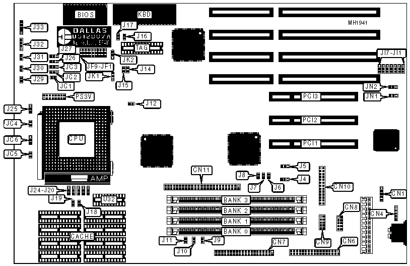
CONNECTIONS | |||
Purpose | Location | Purpose | Location |
Bus mouse connector | CN1 | IDE LED | J11 |
P/S2 mouse connector | CN4 | Green power supply connector | J16 |
Floppy drive interface | CN6 | Turbo switch | J29 |
IDE connector | CN7 | Turbo LED | J30 |
Serial port 1 | CN8 | Reset switch | J31 |
Serial port 2 | CN9 | Speaker | J32 |
Parallel port | CN10 | Power LED & keylock | J33 |
SCSI connector | CN11 | PCI slots | PCI 1, 2, & 3 |
SCSI busy LED | J7 | 3.3V daughter board (80486DX4) | PS3V |
USER CONFIGURABLE SETTINGS | |||
Function | Jumper | Position | |
» | CPU generate parity | J4 | pins 1 & 2 closed |
DPU generate parity | J4 | pins 2 & 3 closed | |
» | Do not force parity error | J5 | pins 1 & 2 closed |
Force parity error | J5 | pins 2 & 3 closed | |
» | SCSI enable | J6 | closed |
SCSI disable | J6 | open | |
» | SCSI power source from peripheral device | J8 | open |
SCSI power source from system | J8 | closed | |
IDE connector pin 27 linked to IOCHRDY signal | J9 | closed | |
IDE connector pin 27 open | J9 | open | |
IDE connector pin 28 linked to BALE signal | J10 | closed | |
IDE connector pin 28 open | J10 | open | |
» | Normal operation | J17 | Open |
Clear password | J17 | closed | |
» | Saturn B-step chip | J23 | pins 1 & 2 closed |
Saturn II/II-50 | J23 | pins 2 & 3 closed | |
» | Cache set at 256K | J24 | pins 2 & 3 closed |
Cache set at 64K | J24 | pins 1 & 2 closed | |
Level 2 write-back cache | J25 | pins 1 & 2 closed | |
Level 2 write-through cache | J25 | pins 2 & 3 closed | |
» | 80486DX4 2.5X mode | J26 | pins 2 & 3 closed |
80486DX4 2X mode | J26 | pins 1 & 2 closed | |
80486DX4 3X mode | J26 | open | |
» | Pentium Overdrive internal write-back cache | J27 | pins 1 & 2 closed |
Pentium Overdrive internal write-through cache | J27 | pins 2 & 3 closed | |
» | No cache wait state | JF3 | pins 2 & 3 closed |
One cache wait state | JF3 | pins 1 & 2 closed | |
Saturn II/II-50 chipset with SL-enhan/DX4/Pentium overdrive | JF9 | pins 2 & 3 closed | |
Saturn II/II-50 chipset with other CPUs | JF9 | pins 1 & 2 closed | |
Saturn II/II-50 chipset for Saturn B-step chipset use | JF9 | open | |
» | PCI SCSI IRQ at IRQ9 | JN1 | pins 1 & 2 closed |
PCI SCSI IRQ at IRQ11 | JN1 | pins 2 & 3 closed | |
DRAM CONFIGURATION | ||||
Size | Bank 0 | Bank 1 | Bank 2 | Bank 3 |
2MB | (1) 256K x 36 | (1) 256K x 36 | NONE | NONE |
4MB | (1) 256K x 36 | (1) 256K x 36 | (1) 256K x 36 | (1) 256K x 36 |
8MB | (1) 1M x 36 | (1) 1M x 36 | NONE | NONE |
10MB | (1) 1M x 36 | (1) 1M x 36 | (1) 256K x 36 | (1) 256K x 36 |
16MB | (1) 1M x 36 | (1) 1M x 36 | (1) 1M x 36 | (1) 1M x 36 |
32MB | (1) 4M x 36 | (1) 4M x 36 | NONE | NONE |
34MB | (1) 4M x 36 | (1) 4M x 36 | (1) 1M x 36 | (1) 256K x 36 |
40MB | (1) 4M x 36 | (1) 4M x 36 | (1) 1M x 36 | (1) 1M x 36 |
64MB | (1) 4M x 36 | (1) 4M x 36 | (1) 4M x 36 | (1) 4M x 36 |
64MB | (1) 16M x 36 | (1) 16M x 36 | NONE | NONE |
DRAM CONFIGURATION (CONTINUED) | ||||
Size | Bank 0 | Bank 1 | Bank 2 | Bank 3 |
66MB | (1) 16M x 36 | (1) 16M x 36 | (1) 256K x 36 | (1) 256K x 36 |
72MB | (1) 16M x 36 | (1) 16M x 36 | (1) 1M x 36 | (1) 1M x 36 |
96MB | (1) 16M x 36 | (1) 16M x 36 | (1) 16M x 36 | (1) 16M x 36 |
128MB | (1) 16M x 36 | (1) 16M x 36 | (1) 16M x 36 | (1) 16M x 36 |
Note:A {(1) 32M x 36} is a double RAS SIMM. | ||||
CACHE CONFIGURATION | |||
Size | Data RAM | TAG RAM | U32 (dirty bit) |
64KB | (8) 8K x 8 | (1) 1K x 8 | 64K x 1 |
256KB | (8) 32K x 8 | (1) 32K x 8 | 64K x 1 |
CACHE JUMPER CONFIGURATION | ||||
Size | J14 | J15 | J18 | J19 |
64KB | Open | Open | Open | Open |
256KB | Closed | Closed | Closed | Closed |
CACHE INTERLEAVE CONFIGURATION | |||
Type | J20 | J21 | J22 |
Interleave | pins 2 & 3 closed | pins 1 & 2 closed | pins 1 & 2 closed |
Standard | pins 1 & 2 closed | pins 2 & 3 closed | pins 2 & 3 closed |
Note:Interleave setting is for the Saturn II-50 chipset only. | |||
CPU TYPE CONFIGURATION | ||
Type | JC1 | JC2, JC3 |
80486SX | Open | pins 2 & 3 |
80486DX | Open | pins 1 & 2 |
80486DX2 | Open | pins 1 & 2 |
80486DX4 | Open | pins 1 & 2 |
Pentium Overdrive | Closed | pins 1 & 2 |
CPU TYPE CONFIGURATION (CONTINUED) | |||
Type | JC4, J12 | JC5 | JC6 |
80486SX 1 | Closed | Open | pins 1 & 2 |
80486SX 2 | Closed | Open | pins 1 & 2 |
80486DX 1 | Closed | Open | pins 1 & 2 |
80486DX 2 | Closed | Open | pins 1 & 2 |
80486DX2 1 | Closed | Open | pins 1 & 2 |
80486DX2 2 | Closed | Open | pins 1 & 2 |
80486DX4 1 | Closed | Open | pins 1 & 2 |
80486DX4 2 | Closed | Closed | pins 2 & 3 |
CPU TYPE CONFIGURATION (CONTINUED) | |||
Type | JC4, J12 | JC5 | JC6 |
SL enhanced 1 | Closed | open | pins 1 & 2 |
SL enhanced 2 | Closed | closed | pins 2 & 3 |
Pentium Overdrive 1 | Open | open | pins 1 & 2 |
Pentium Overdrive 2 | Open | closed | pins 2 & 3 |
Note: 1 denotes Saturn B-step chipset used with CPU. | |||
| 2 denotes Saturn II/II-50 chipset used with CPU. | |||
CPU CLOCK (VT8225N) CONFIGURATION | ||
Speed | JK1 | JK2 |
CLK2 50 Mhz | pins 1 & 2 closed | pins 2 & 3 closed |
CLK2 66.6 Mhz | pins 2 & 3 closed | pins 1 & 2 open |
CPU SPEED CONFIGURATION | ||
Speed | JF6 | JF7 |
Reserved | pins 2 & 3 | pins 1 & 2 |
25MHz | pins 1 & 2 | pins 1 & 2 |
33Mhz | pins 1 & 2 | pins 2 & 3 |
50iMHz | pins 1 & 2 | pins 1 & 2 |
50iMHz 1 | pins 2 & 3 | pins 2 & 3 |
66iMHz | pins 1 & 2 | pins 2 & 3 |
Note: 1 denotes Saturn II-50 chipset only. | ||
PCI1 IRQ SELECTION | ||
Jumper | IRQ | Setting |
JI1 | IRQ5 | pins 1 & 2 closed |
JI2 | IRQ9 | pins 1 & 2 closed |
JI3 | IRQ10 | pins 1 & 2 closed |
JI4 | IRQ11 | pins 1 & 2 closed |
JI5 | IRQ12 | pins 1 & 2 closed |
JI6 | IRQ14 | pins 1 & 2 closed |
JI7 | IRQ15 | pins 1 & 2 closed |
PCI2 & PCI3 IRQ SELECTION | ||
Jumper | IRQ | Setting |
JI1 | IRQ5 | pins 2 & 3 closed |
JI2 | IRQ9 | pins 2 & 3 closed |
JI3 | IRQ10 | pins 2 & 3 closed |
JI4 | IRQ11 | pins 2 & 3 closed |
JI5 | IRQ12 | pins 2 & 3 closed |
JI6 | IRQ14 | pins 2 & 3 closed |
JI7 | IRQ15 | pins 2 & 3 closed |
TAG ADDRESS CONFIGURATION | ||
Address | JF1 | JF2 |
8-bit | pins 1 & 2 closed | pins 1 & 2 closed |
7-bit | pins 1 & 2 closed | pins 2 & 3 closed |
9-bit | pins 2 & 3 closed | pins 1 & 2 closed |
Reserved | pins 2 & 3 closed | pins 2 & 3 closed |
MISCELLANEOUS TECHNICAL NOTE |
Note:1. When using the PCI1 slot on the mainboard, jumper choice should only be limited to pins 1 & 2 of jumpers JI1 to JI7 |
2. When using PCI2 or PCI3 slots on the mainboard, jumper choice should only be limited to pins |
2 & 3 of jumpers JI1 to JI7. |
3. When using the Saturn B-step chipset, PCI1 slot serves as the master slot while PCI2 and PCI |
3 slots serve as slave slots. |
4. When using the Saturn II/II-50 chipset, PCI1, PCI2, PCI3 slots can serve both as master or |
slave slot. |
My Books

