


386SX-25/33DNB/DCB AIO Motherboard Settings and Configuration
DIAMOND FLOWER, INC.
386SX-25/33DNB/DCB AIO
Processor | 80386SX |
Processor Speed | 25/33MHz |
Chip Set | Diamond Flower/Acer |
Max. Onboard DRAM | 16MB |
SRAM Cache | None |
BIOS | AMI |
Dimensions | 330mm x 218mm |
I/O Options | Floppy drive interface, IDE interface, parallel port, PS/2 mouse port, riser card slot, serial ports (2) VGA feature connector, VGA port |
NPU Options | 80387SX |
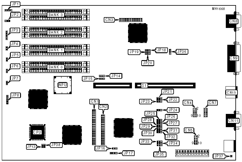
CONNECTIONS | |||
Purpose | Location | Purpose | Location |
IDE interface | CN1 | Keyboard connector | JP3 |
Floppy drive interface | CN2 | Turbo LED | JP4 |
VGA Feature connector | CN3 | Turbo switch | JP5 |
Serial port (COM2) | CN7 | Reset switch | JP6 |
VGA port | CN8 | IDE interface LED | JP7 |
Parallel port | CN9 | Power LED & keylock | JP8 |
PS/2 mouse port | CN10 | External battery | JP17 |
Serial port (COM1) | CN11 | Riser Card | S1 |
Speaker | JP2 |
|
|
Note: JP5 is located on the 386SX-25DNB/DCB AIO system board only. JP38 is located on the 386SX-33DNB/DCB AIO system board only. | |||
USER CONFIGURABLE SETTINGS | |||
Function | Jumper | Position | |
» | Speaker select internal | JP1 | pins 1 & 2 closed |
| Speaker select external | JP1 | pins 2 & 3 closed |
» | Monitor type select color | JP13 | closed |
| Monitor type select monochrome | JP13 | open |
» | Factory configured - do not alter | JP14 | pins 1 & 2 closed |
» | Factory configured - do not alter | JP15 | pins 2 & 3 closed |
» | Battery select external | JP16 | pins 2 & 3 closed |
| Battery select internal | JP16 | pins 1 & 2 closed |
» | Parallel port select IRQ7 | JP24 | pins 1 & 2 closed |
| Parallel port select IRQ5 | JP24 | pins 2 & 3 closed |
» | Factory configured - do not alter | JP30 | pins 1 & 2 closed |
» | Floppy disk drive enabled | JP31 | closed |
| Floppy disk drive disabled | JP31 | open |
» | IDE interface enabled | JP32 | pins 1 & 2 closed |
| IDE interface disabled | JP32 | pins 2 & 3 closed |
» | Factory configured - do not alter | JP37 | Open |
» | Factory configured - do not alter | JP38 | N/A |
DRAM CONFIGURATION | ||||
Size | Bank 0 | Bank 1 | Bank 2 | Bank 3 |
512KB | (2) 256K x 9 | NONE | NONE | NONE |
1MB | (2) 256K x 9 | (2) 256K x 9 | NONE | NONE |
1.5MB | (2) 256K x 9 | (2) 256K x 9 | (2) 256K x 9 | NONE |
2MB | (2) 1M x 9 | NONE | NONE | NONE |
2MB | (2) 256K x 9 | (2) 256K x 9 | (2) 256K x 9 | (2) 256K x 9 |
2.5MB | (2) 1M x 9 | (2) 256K x 9 | NONE | NONE |
3MB | (2) 1M x 9 | (2) 256K x 9 | (2) 256K x 9 | NONE |
4MB | (2) 1M x 9 | (2) 1M x 9 | NONE | NONE |
4.5MB | (2) 1M x 9 | (2) 1M x 9 | (2) 256K x 9 | NONE |
5MB | (2) 1M x 9 | (2) 1M x 9 | (2) 256K x 9 | (2) 256K x 9 |
6MB | (2) 1M x 9 | (2) 1M x 9 | (2) 1M x 9 | NONE |
8MB | (2) 1M x 9 | (2) 1M x 9 | (2) 1M x 9 | (2) 1M x 9 |
8MB | (2) 4M x 9 | NONE | NONE | NONE |
10MB | (2) 4M x 9 | (2) 1M x 9 | NONE | NONE |
16MB | (2) 4M x 9 | (2) 4M x 9 | NONE | NONE |
SERIAL PORT CONFIGURATION | |||||
COM1 (CN11) | COM2 (CN7) | JP27 | JP28 | JP29 | |
» | COM1 | COM2 | Pins 1 & 2 closed | Pins 1 & 2 closed | Pins 1 & 2 closed |
| COM1 | Disabled | Pins 1 & 2 closed | Pins 2 & 3 closed | Pins 1 & 2 closed |
| COM2 | COM1 | Pins 2 & 3 closed | Pins 1 & 2 closed | Pins 1 & 2 closed |
| COM2 | Disabled | Pins 1 & 2 closed | Pins 2 & 3 closed | Pins 2 & 3 closed |
| Disabled | COM1 | Pins 2 & 3 closed | Pins 1 & 2 closed | Pins 2 & 3 closed |
| Disabled | COM2 | Pins 1 & 2 closed | Pins 1 & 2 closed | Pins 2 & 3 closed |
| Disabled | Disabled | Open | Pins 2 & 3 closed | Pins 2 & 3 closed |
SERIAL PORT NORMAL/FORCED TRUE CONFIGURATION | ||||
COM1 | JP33 | JP34 | JP35 | |
» | Normal | Pins 1 & 2 closed | Pins 1 & 2 closed | Pins 1 & 2 closed |
| Forced True | Pins 2 & 3 closed | Pins 2 & 3 closed | Pins 2 & 3 closed |
SERIAL PORT NORMAL/FORCED TRUE CONFIGURATION | ||||
COM2 | JP21 | JP22 | JP23 | |
» | Normal | Pins 1 & 2 closed | Pins 1 & 2 closed | Pins 1 & 2 closed |
| Forced True | Pins 2 & 3 closed | Pins 2 & 3 closed | Pins 2 & 3 closed |
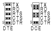
SERIAL PORT'S DTE/DCE CONFIGURATION | |
Primary serial port CN5 | Secondary serial port CN4 |
|
|
PARALLEL PORT CONFIGURATION | |||
LPT | JP25 | JP26 | |
» | 1 | Pins 2 & 3 closed | Pins 1 & 2 closed |
| 2 | Pins 1 & 2 closed | Pins 1 & 2 closed |
| 3 | Pins 1 & 2 closed | Pins 2 & 3 closed |
| Disabled | Pins 2 & 3 closed | Pins 2 & 3 closed |
LOCAL BUS VGA CONFIGURATION | |||||
Mode | JP18 | JP19 | JP20 | JP36 | |
» | Enabled | Pins 2 & 3 closed | Pins 2 & 3 closed | Pins 2 & 3 closed | Pins 1 & 2 closed |
| Disabled | Pins 1 & 2 closed | Pins 1 & 2 closed | Pins 1 & 2 closed | Pins 2 & 3 closed |


My Books

