


POWEREDGE SP 5XX/POWEREDGE XE 5XX/OMNIPLEX 5XX-ME Motherboard Settings and Configuration
DELL COMPUTER CORPORATION
POWEREDGE SP 5XX/POWEREDGE XE 5XX/OMNIPLEX 5XX-ME
Processor | Pentium |
Processor Speed | 60/66MHz |
Chip Set | Intel |
Max. Onboard DRAM | 192MB |
Cache | 256KB |
BIOS | Intel |
Dimensions | 330mm x 218mm |
I/O Options | 32-bit riser card, floppy drive interface, IDE interface, parallel port, PS/2 mouse port, SCSI connector, serial ports (2), VGA port |
NPU Options | None |
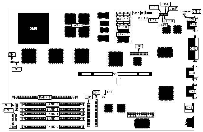
CONNECTIONS | |||
Purpose | Location | Purpose | Location |
VGA port | CN1 | Floppy drive interface | CN8 |
Parallel port | CN2 | External battery | CN9 |
Serial port 1 | CN3 | Speaker | CN10 |
Serial port 2 | CN4 | Chassis fan power | CN11 |
PS/2 mouse port | CN5 | Front panal connector | CN13 |
Feature connector | CN6 | IDE interface LED | CN16 |
IDE interface | CN7 | 32-bit riser card slot | S1 |
USER CONFIGURABLE SETTINGS | |||
Function | Jumper/Switch | Position | |
» | Factory configured - do not alter | J15A | Open |
» | EISA configuration utility settings normal operation | J15B | Open |
EISA configuration utility settings clear | J15B | Closed | |
» | Factory configured - do not alter | J15C | Open |
» | Factory configured - do not alter | J15D | Open |
» | Factory configured - do not alter | JP1 | Closed |
» | Integrated SCSI host adapter disabled | SCSI | Closed |
Integrated SCSI host adapter enabled | SCSI | Open | |
» | Factory configured - do not alter | SMI | Closed |
» | Monitor type built in VGA enabled | SW1/1 | On |
Monitor type built in VGA disabled | SW1/1 | Off | |
» | System password enabled | SW1/2 | On |
System password disabled | SW1/2 | Off | |
» | I/O controller uses addresses 26Eh to 26Fh | SW1/3 | On |
I/O controller uses addresses 398h to 399h | SW1/3 | Off | |
» | Flash BIOS update enabled | SW1/4 | On |
Flash BIOS update disabled | SW1/4 | Off | |
DRAM CONFIGURATION | |||
Size | Bank 0 | Bank 1 | Bank 2 |
8MB | (2) 1M x 36 | NONE | NONE |
16MB | (2) 1M x 36 | (2) 1M x 36 | NONE |
24MB | (2) 1M x 36 | (2) 1M x 36 | (2) 1M x 36 |
32MB | (2) 4M x 36 | NONE | NONE |
40MB | (2) 4M x 36 | (2) 1M x 36 | NONE |
48MB | (2) 4M x 36 | (2) 1M x 36 | (2) 1M x 36 |
64MB | (2) 4M x 36 | (2) 4M x 36 | NONE |
DRAM CONFIGURATION (CONT.) | |||
Size | Bank 0 | Bank 1 | Bank 2 |
72MB | (2) 4M x 36 | (2) 4M x 36 | (2) 1M x 36 |
96MB | (2) 4M x 36 | (2) 4M x 36 | (2) 4M x 36 |
128MB | (2) 16M x 36 | NONE | NONE |
136MB | (2) 16M x 36 | (2) 1M x 36 | NONE |
144MB | (2) 16M x 36 | (2) 1M x 36 | (2) 1M x 36 |
160MB | (2) 16M x 36 | (2) 4M x 36 | NONE |
192MB | (2) 16M x 36 | (2) 4M x 36 | (2) 4M x 36 |
CPU SPEED CONFIGURATION | ||
Speed | J15F | J15E |
60MHz | Closed | Open |
66MHz | Open | Closed |
VIDEO MEMORY CONFIGURATION | ||
Size | Bank 0 | Bank 1 |
1M | (4) 44256 | NONE |
2M | (4) 44256 | (4) 44256 |
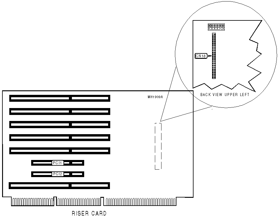
CONNECTIONS | |||
Purpose | Location | Purpose | Location |
SCSI connector | CN18 | 32-bit PCI local bus slot | PCI2 |
32-bit PCI local bus slot | PCI1 | ||
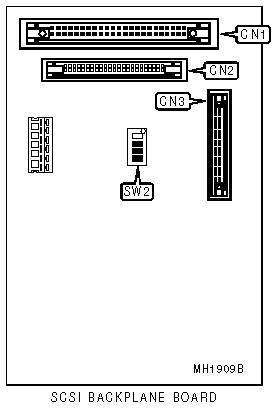
CONNECTIONS | |||
Purpose | Location | Purpose | Location |
Narrow SCSI port | CN1 | Port for Thermal Monitoring board | CN3 |
Wide SCSI port | CN2 | ||
SCSI ID CONFIGURATION | |||
SCSI IDs | Switch | DSA Host Adapter | Non-DSA Host Adapter |
Bay A = ID4 | SW2/switch 1 | On | Off |
Bay B = ID1 | SW2/switch 2 | Off | Off |
Bay C = ID2 | SW2/switch 3 | Off | Off |
Bay D = ID3 | SW2/switch 4 | On | Off |
MISCELLANEOUS TECHNICAL NOTE |
The SCSI backplane board is an option and may not always be present on the mainboard. |
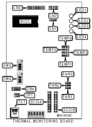
CONNECTIONS | |||
Purpose | Location | Purpose | Location |
Speaker | CN1 | SCSI connector | SCSIA |
Panel connector | CN2 | SCSI connector | SCSIB |
manufacturer’s connector | CN3 | Temp connector | TEMP1 |
Connection to system board | CN4 | Temp connector | TEMP2 |
Fan | FAN1 | Temp connector | TEMP3 |
Fan | FAN2 | Temp connector | TEMP4 |
Fan | FAN3 | Test connector | TST |
THERMAL MONITORING BOARD CONFIGURATION | |
Thermal monitoring board installed | Setting |
SW3/switch 1 | On |
SW3/switch 2 | On |
SW3/switch 3 | On |
SW3/switch 4 | Off |
SW4/switch 1 | On |
SW4/switch 2 | Off |
SW4/switch 3 | On |
SW4/switch 4 | Off |
LED CONFIGURATION | |
LED | Function |
LED1 | Thermal monitoring |
LED2 | Temperature |
LED3 | Fan |
LED4 | Power |
MISCELLANEOUS TECHNICAL NOTE |
JP1 is factory configured and should not be altered. |


My Books

