IPCCPU Motherboard Settings and Configuration
DECISION COMPUTER INTERNATIONAL CO., LTD.
IPCCPU
Processor | Z80 |
Processor Speed | 9.83MHz |
Chipset | Unidentified |
Maximum Onboard Memory | 32KB SRAM/32KB EPROM |
BIOS | Unidentified |
Video Chipset | Unidentified |
Maximum Video Memory | Unidentified |
Video Types Supported | LCD display |
Highest Resolution Supported | 4 x 20 (text only) |
I/O Options | Serial ports (2), LCD video out, expansion bus |
Dimensions | 80 x 100mm |
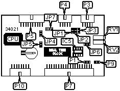
CONNECTIONS | |||
Function | Label | Function | Label |
External battery connector | JP6 | Expansion bus | P7 |
5V DC power in | P1 | Reset switch | P9 |
Generic serial port 2 | P3 | LCD video out | P10 |
Generic serial port 1 | P4 | IC5 voltage adjustment | RV1 |
Keyboard connector (IPCKEY/IPCKEYM) | P5 | LCD contrast adjustment | RV2 |
Note:RV1 should be adjusted so that pin 4 of IC5 is 1.3V and pin 5 is equal to the voltage going into P1. P3 and P4 are not RS-232 serial. The interface type is provided by one of the boards on the sections for the IPC232ST, IPC232CL, and IPC422/485 cards. | |||
USER CONFIGURABLE SETTINGS | |||
Setting | Label | Position | |
| » | System interrupt timers enabled | JP1 | Closed |
System interrupt timers disabled | JP1 | Open | |
| » | MAX960 chip not installed in IC5 | JP2 | Closed |
MAX960 chip installed in IC5 | JP2 | Open | |
| » | Watchdog timer disabled | JP3 | Open |
Watchdog timer enabled | JP3 | Closed | |
| » | Power fail interrupt disabled | JP4 | Open |
Power fail interrupt enabled | JP4 | Closed | |
| » | Real-time clock interrupt disabled | JP5 | Open |
Real-time clock interrupt enabled | JP5 | Closed | |
| » | Keyboard enabled | JP7 | Pins 2 & 3 closed |
Keyboard disabled | JP7 | Pins 1 & 2 closed | |
Card Type | Serial |
Chipset | Unidentified |
I/O Options | Serial port |
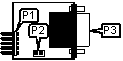
CONNECTIONS | |||
Function | Label | Function | Label |
Header to main board P3 or P4 | P1 | RS-232 or current loop serial port | P3 |
DC power in | P2 | ||
IPCCPU (IPC422/485 SERIAL CARD)
Card Type | Serial |
Chipset | Unidentified |
I/O Options | Serial port |
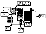
CONNECTIONS | |||
Function | Label | Function | Label |
Header to main board P3 or P4 | P1 | RS-422 or RS-485 serial port | P3 |
DC power in | P2 | ||
SERIAL PORT CONFIGURATION | ||
Setting | JP2 | JP3 |
RS-422 | Pins 2 & 3 closed | Pins 2 & 3 closed |
RS-485 | Pins 1 & 2 closed | Open |
RECEIVER ENABLE SELECTION | |||
Setting | JP1/A | JP1/B | JP1/C |
RTS enables receiver | Closed | Open | Open |
DTR enables receiver | Open | Open | Closed |
Receiver always enabled | Open | Closed | Open |
Note:The receiver may not be always enabled in RS-485 mode. | |||
MISCELLANEOUS TECHNICAL NOTE |
No information is available on the IPC232FS card. |
My Books

