ISA486GXi MODEL I433A Motherboard Settings and Configuration
ACER, INC.
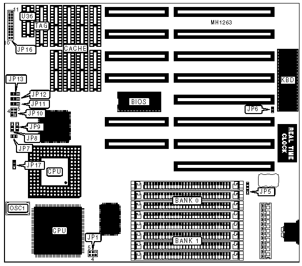
ISA486GXi MODEL I433A
Processor | 80486SX/80487SX/80486DX/ODP486SX/80486DX2 |
Processor Speed | 20/25/33/50(internal)/66(internal) |
Chip Set | ALI |
Max. Onboard DRAM | 32MB |
SRAM Cache | 64/256KB |
BIOS | Acer |
Dimensions | 220mm x 240mm |
I/O Options | None |
NPU Options | None |
CONNECTIONS | |||
Purpose | Location | Purpose | Location |
External battery | JP5 | Turbo LED | JP16/12 & 13 |
Power LED & keylock | JP16/1 - 5 | Turbo switch | JP16/15 - 17 |
Speaker | JP16/7 - 10 | Reset switch | JP16/19 & 20 |
SRAM CONFIGURATION | ||||||
Size | Cache | TAG | (U36) | JP10 | JP11 | JP12 |
64KB | (8) 8K x 8 | (1) 8K x 8 | (1) 16K x 4 | open | pins 2 & 3 | pins 1 & 2 |
64KB | (8) 8K x 8 | (1) 8K x 8 | NONE | open | pins 1 & 2 | pins 2 & 3 |
256KB | (8) 32K x 8 | (1) 32K x 8 | (1) 16K x 4 | closed | pins 2 & 3 | pins 1 & 2 |
256KB | (8) 32K x 8 | (1) 32K x 8 | NONE | closed | pins 1 & 2 | pins 2 & 3 |
Note:Pins designated should be in the closed position. JP10 is closed by shorting pins 1 & 2, 3 & 4, and 5 & 6. | ||||||
USER CONFIGURABLE SETTINGS | |||
Function | Jumper | Position | |
| » | CMOS memory normal operation | JP6 | open |
CMOS memory clear | JP6 | closed | |
System automatically detects CPU type installed | JP7 | closed | |
System detects only 486SX/DX CPUs | JP7 | open | |
| » | Factory configured - do not alter | JP8 | pins 1 & 2 closed |
| » | Factory configured - do not alter | JP13 | pins 1 & 2 closed |
| » | Factory configured - do not alter | JP17 | open |
DRAM CONFIGURATION | ||
Size | Bank 0 | Bank 1 |
1MB | (4) 256K x 9 | NONE |
2MB | (4) 256K x 9 | (4) 256K x 9 |
2MB | (4) 512K x 9 | NONE |
4MB | (4) 512K x 9 | (4) 512K x 9 |
4MB | (4) 1M x 9 | NONE |
5MB | (4) 1M x 9 | (4) 256K x 9 |
6MB | (4) 512K x 9 | (4) 1M x 9 |
8MB | (4) 1M x 9 | (4) 1M x 9 |
16MB | (4) 4M x 9 | NONE |
17MB | (4) 256K x 9 | (4) 4M x 9 |
18MB | (4) 512K x 9 | (4) 4M x 9 |
20MB | (4) 1M x 9 | (4) 4M x 9 |
32MB | (4) 4M x 9 | (4) 4M x 9 |
CPU SPEED CONFIGURATION FOR CH9001 SYSTEM CLOCK CHIP | ||
CPU Speed | JP1 | JP9 |
20MHz | pins 1 & 2 closed | pins 2 & 3 closed |
25MHz | open | pins 2 & 3 closed |
33MHz | pins 3 & 4 closed | pins 2 & 3 closed |
40MHz | pins 1 & 2 and 5 & 6 closed | pins 1 & 2 closed |
50MHz | pins 5 & 6 closed | pins 1 & 2 closed |
CPU SPEED CONFIGURATION FOR IMISC425 SYSTEM CLOCK CHIP | ||
CPU Speed | JP1 | JP9 |
20MHz | pins 1 & 2 and 3 & 4 closed | pins 2 & 3 closed |
25MHz | pins 3 & 4 closed | pins 2 & 3 closed |
33MHz | pins 1 & 2 closed | pins 2 & 3 closed |
40MHz | pins 1 & 2, 3 & 4, and 5 & 6 closed | pins 1 & 2 closed |
50MHz | pins 5 & 6 closed | pins 1 & 2 closed |
My Books

