


FOM-400 modem/telephone/ISDN Settings and Configuration
RAD DATA COMMUNICATIONS
FOM-400
Card Type | T1/E1 signal converter |
Chipset | Unidentified |
Topology | Peer-Peer |
Wire Type | Fiber optic cable |
T1/E1 Transfer Rate | 1.544Mbps/2.048Mbps |
T1/E1 Protocol | AMI, HDB3 |
Frame Type | Unidentified |
Data Bus | Proprietary |
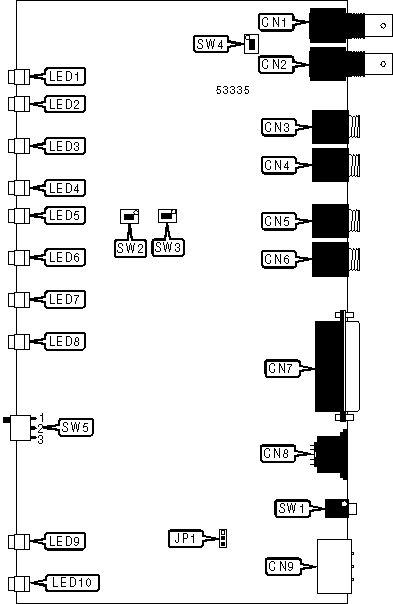
CONNECTIONS | |||
Function | Label | Function | Label |
T1/E1 line in | CN1 | Primary fiber optic transmit connector | CN6 |
T1/E1 line out | CN2 | Control port (see pinout below) | CN7 |
Secondary fiber optic receive connector | CN3 | DC power in | CN8 |
Secondary fiber optic transmit connector | CN4 | AC power in | CN9 |
Primary fiber optic receive connector | CN5 | Power switch | SW1 |
CN7 PINOUT | |||
Function | Pin | Function | Pin |
Chassis ground | 1 | Primary/secondary fiber optic channel indicator signal | 14 |
Not used | 2 | Not used | 15 |
Not used | 3 | T1/E1 connection broken relay | 16 |
T1/E1 connection broken signal | 4 | Not used | 17 |
Not used | 5 | Not used | 18 |
Not used | 6 | T1/E1 connection broken relay | 19 |
Signal ground | 7 | Alarm condition signal | 20 |
Not used | 8 | Not used | 21 |
Not used | 9 | Primary/secondary fiber optic channel selection | 22 |
Not used | 10 | Secondary fiber optic connection broken signal | 23 |
Not used | 11 | Not used | 24 |
Not used | 12 | Primary fiber optic connection broken signal | 25 |
Not used | 13 | Not used | |
USER CONFIGURABLE SETTINGS | ||
Setting | Label | Position |
Signal ground connected to chassis ground | JP1 | Pins 1 & 2 closed |
Signal ground not connected to chassis ground | JP1 | Pins 2 & 3 closed |
Primary fiber optic channel set for short-range operation | SW2 | On |
Primary fiber optic channel set for long-range operation | SW2 | Off |
Secondary fiber optic channel set for short-range operation | SW3 | On |
Secondary fiber optic channel set for long-range operation | SW3 | Off |
T1/E1 interface set for 100ohm or 120ohm balanced cable | SW4 | On |
T1/E1 interface set for 75ohm unbalanced cable | SW4 | Off |
FIBER OPTIC CHANNEL SELECTION | ||
Setting | SW5 | |
| » | Channel selected by control port | Position 2 |
Primary channel active | Position 1 | |
Secondary channel active | Position 3 | |
DIAGNOSTIC LED(S) | |||
LED | Color | Status | Condition |
LED1 | Green | On | AC power source is connected at CN9 |
LED1 | Green | Off | AC power source is not connected at CN9 |
LED2 | Green | On | Backup DC power is connected to CN8 |
LED2 | Green | Off | Backup DC power is not connected to CN8 |
LED3 | Red | On | Internal power supply failed |
LED3 | Red | Off | Internal power supplies are good |
LED4 | Green | On | DSU is receiving data |
LED4 | Green | Off | DSU is not receiving data |
LED5 | Green | On | DSU is transmitting data |
LED5 | Green | Off | DSU is not transmitting data |
LED6 | Red | On | Fiber optic synchronization lost |
LED6 | Red | Off | Fiber optic synchronization good |
LED7 | Yellow | On | Primary fiber optic channel in use |
LED7 | Yellow | Off | Primary fiber optic channel not in use |
LED8 | Red | On | Primary fiber optic channel receive level less than -39dBm |
LED8 | Red | Off | Primary fiber optic channel receive level more than -39dBm |
LED9 | Yellow | On | Secondary fiber optic channel in use |
LED9 | Yellow | Off | Secondary fiber optic channel not in use |
LED10 | Red | On | Secondary fiber optic channel receive level less than -39dBm |
LED10 | Red | Off | Secondary fiber optic channel receive level more than -39dBm |


My Books

