


ASMI-24 SLAVE (DC POWER) modem/telephone/ISDN Settings and Configuration
RAD DATA COMMUNICATIONS, INC.
ASMI-24 SLAVE (DC POWER)
Card Type | Modem (synchronous) |
Chipset | Unidentified |
I/O Options | Control box connector |
Maximum Data Rate | 144Kbps |
Data Modulation | Proprietary (PR4) |
Data Bus | Serial |
s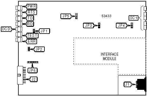
CONNECTIONS | |||
Function | Label | Function | Label |
DC power in | J1 | Line out - see pinout below | SC1 |
Control box connector | J2 | ||
SC1 PINOUT | |||
Function | Screw | Function | Screw |
Ground | 1 | Transmit signal | 4 |
Receive signal | 2 | Transmit signal | 5 |
Receive signal | 3 | ||
USER CONFIGURABLE SETTINGS | ||
Setting | Label | Position |
í Modem is in management slave mode | JP1 | Closed |
Modem is in management master mode | JP1 | Open |
í ASM-24 mode disabled | JP2 | Open |
ASM-24 mode enabled | JP2 | Closed |
í Transmit level set to 0dBm | JP3 | Pins 1 & 2 closed |
Transmit level set to -6dBm | JP3 | Pins 2 & 3 closed |
í Signal ground connected to chassis ground | JP4 | Pins 2 & 3 closed |
Signal ground not connected to chassis ground | JP4 | Pins 1 & 2 closed |
í Receive level set to 0dBm | JP5 | Pins 1 & 2 closed |
Receive level set to -6dBm | JP5 | Pins 2 & 3 closed |
í Factory configured - do not alter (jumper storage) | JP6 | N/A |
DIAGNOSTIC LED(S) | |||
LED | Color | Status | Condition |
PWR | Green | On | Power is on |
PWR | Green | Off | Power is off |
RTS | Yellow | On | RTS signal is high |
RTS | Yellow | Off | RTS signal is low |
TD | Yellow | On | Modem is transmitting SPACE |
TD | Yellow | Blinking | Modem is transmitting data |
TD | Yellow | Off | Modem is not transmitting data |
RD | Yellow | On | Modem is receiving SPACE |
RD | Yellow | Blinking | Modem is receiving data |
RD | Yellow | Off | Modem is not receiving data |
DCD | Yellow | On | Carrier signal detected |
DCD | Yellow | Off | Carrier signal not detected |
TEST | Red | On | Modem is in test mode |
TEST | Red | Off | Modem is not in test mode |
ERR | Yellow | On | Error detected in received test pattern |
ERR | Yellow | Off | No errors detected in received test pattern |
MISCELLANEOUS TECHNICAL NOTES |
Available serial interface modules include V.24, V.35, V.36/RS-530, X.21, and G.730 interface types. Information on all except the G.730 interface modules is unidentified. |
Card Type | Serial |
Chipset | Unidentified |
I/O Options | Serial port |

CONNECTIONS | |
Function | Label |
G.703 serial port - see pinout below | SC1 |
SC1 PINOUT | |||
Function | Screw | Function | Screw |
Ground | 1 | Transmit signal | 4 |
Receive signal | 2 | Transmit signal | 5 |
Receive signal | 3 | ||
USER CONFIGURABLE SETTINGS | ||
Setting | Label | Position |
Serial port uses receive FIFO | JP1 | Pins 2 & 3 closed |
Serial port uses transmit FIFO | JP1 | Pins 1 & 2 closed |
Card Type | Serial |
Chipset | Unidentified |
I/O Options | Serial port |
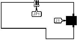
CONNECTIONS | |
Function | Label |
G.703 serial port via RJ-45 connector | J1 |
USER CONFIGURABLE SETTINGS | ||
Setting | Label | Position |
Serial port uses receive FIFO | JP1 | Pins 2 & 3 closed |
Serial port uses transmit FIFO | JP1 | Pins 1 & 2 closed |


My Books

