1075 modem/telephone/ISDN Settings and Configuration
PATTON ELECTRONICS COMPANY
1075
Card Type | Modem |
Chip Set | Unidentified |
I/O Options | Power, DTE/DCE serial port (15-pin connector), network interface via RJ-45 (RJ-11 optional) connector |
Wiring Type | RJ-45 (RJ-11 optional) shielded twisted pair |
Maximum Data Rate | 64Kbps |
Data Bus | External |
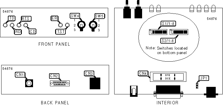
CONNECTIONS | |||||||
Function | Label | Function | Label | ||||
AC power connector | CN1 | Network interface via RJ-45 connector | CN3 | ||||
DTE/DCE port (15-pin connector) | CN2 | DTE/DCE strap | CN4 | ||||
Note: | DTE/DCE strap is default configured for DCE interface. To change the interface to DTE, rotate the strap 180 degrees so the DTE arrows point to the 15-pin connector. | ||||||
USER CONFIGURABLE SETTINGS | ||
Setting | Label | Position |
í Shield connected to signal ground | JP1 | Pins 2 & 3 closed |
Shield not connected to signal ground | JP1 | Pins 1 & 2 closed |
í Factory configured - do not alter | S1/1 | Off |
í Factory configured - do not alter | S1/2 | Off |
í Factory configured - do not alter | S1/3 | Off |
í Factory configured - do not alter | S1/4 | Off |
í Factory configured - do not alter | S1/5 | Off |
í Factory configured - do not alter | S1/6 | Off |
í Factory configured - do not alter | S1/7 | Off |
í Modem responds to V.54 sequence | S1/8 | Off |
Modem ignores V.54 sequence | S1/8 | On |
í Carrier forced high | S2/5 | Off |
Carrier follows terminal | S2/5 | On |
í Factory configured - do not alter | S2/6 | Off |
í Factory configured - do not alter | S2/7 | Off |
í Front panel switches enabled | S2/8 | On |
Front panel switches disabled | S2/8 | Off |
DATA RATE | ||||||
Setting | S2/1 | S2/2 | ||||
32Kbps | Off | On | ||||
56Kbps | On | Off | ||||
í 64Kbps | On | On | ||||
TRANSMIT CLOCK SOURCE | ||
Source | S2/3 | S2/4 |
í Transmit clock generated internally | On | On |
Transmit clock derived from terminal interface | On | Off |
Transmit clock derived from receive line signal | Off | On |
TEST PATTERN GENERATOR | ||
Function | Label | Position |
511 test pattern transmitted | SW4 | 1 |
Normal operation. Test pattern not activated | SW4 | 2 |
511/E test pattern transmitted (intentional errors inserted) | SW4 | 3 |
LOOPBACK TEST SELECTOR | ||
Function | Label | Position |
Remote digital loopback initiated | SW5 | 1 |
Normal operation. Loopback not activated | SW5 | 2 |
Activates local analog loopback | SW5 | 3 |
DIAGNOSTIC LED(S) | |||
LED | Color | Status | Condition |
TD | Red | On | Data is being transmitted (low logic level, device idle) |
TD | Green | On | Data is being transmitted (high logic level) |
TD | Orange | On | Transmitted data is changing rapidly |
TD | None | Off | Data is not being transmitted |
RD | Red | On | Data is being received (low logic level, device idle) |
RD | Green | On | Data is being received (high logic level) |
RD | Orange | On | Received data is changing rapidly |
RD | None | Off | Data is not being received |
RTS | Green | On | RTS signal is high |
RTS | Red | On | RTS signal is low |
CD | Green | On | Carrier signal detected |
CD | Red | On | Carrier signal not detected |
ER | Red | On | Bit error likely in received signal or error detected in 511 or 511/E test pattern |
ER | Red | Off | Error not detected |
TST | Red | On | Device has been placed in test mode by local or remote user |
TST | Red | Off | Device is not conducting a test |
My Books

