


2450 modem/telephone/ISDN Settings and Configuration
PATTON ELECTRONICS COMPANY
2450
Card Type | CSU/DSU |
Chip Set | Unidentified |
I/O Options | Power, DTE/DCE serial port, network interface via RJ-48 connector |
Maximum Data Rate | 64Kbps |
Data Bus | External |
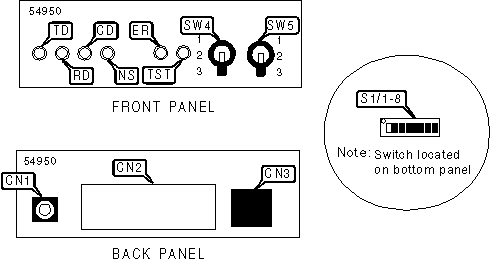
CONNECTIONS | |||
Function | Label | Function | Label |
Power connector | CN1 | Network interface via RJ-48 connector | CN3 |
DTE/DCE port (quick connect module) | CN2 | ||
Note: Quick connect serial interface module can be configured as a V.24/RS-232, V.35, RS422/530, or X.21 port. | |||
USER CONFIGURABLE SETTINGS | |||
Setting | Label | Position | |
| » | Circuit assurance disabled. Transmitter and CTS will operate independent of receiver state | S1/3 | Off |
| Circuit assurance enabled. CTS will go low and the transmitter will be held off if the receiver is in the No signal state or CD is low | S1/3 | On | |
| » | RTS forced high | S1/4 | On |
RTS follows DTE signal | S1/4 | Off | |
| » | 56Kbps mode | S1/5 | Off |
64Kbps mode | S1/5 | On | |
| » | Front panel switches enabled | S1/6 | Off |
Front panel switches disabled | S1/6 | On | |
| » | Modem ignores loopback requests from DTE | S1/7 | On |
| Modem responds to local analog loopback requests from DTE | S1/7 | Off | |
| » | Modem ignores loopback requests from remote | S1/8 | On |
| Modem responds to loopback requests from remote | S1/8 | Off | |
TRANSMIT CLOCK SOURCE | |||
Source | S1/1 | S1/2 | |
| » | Transmit clock derived from receive line signal. Dedicated DDS operation | Off | On |
| Transmit clock derived from receive line signal. Allows remote device to initiate loopback. | On | On | |
Transmit clock generated internally | Off | Off | |
Transmit clock derived from terminal interface | On | Off | |
LOOPBACK TEST SELECTOR | ||
Function | Label | Position |
Remote digital loopback initiated | SW4 | 1 |
Normal operation. Loopback not activated | SW4 | 2 |
Activates local analog loopback | SW4 | 3 |
TEST PATTERN GENERATOR | ||
Function | Label | Position |
511/E test pattern transmitted (intentional errors inserted) | SW5 | 1 |
Normal operation. Test pattern not activated | SW5 | 2 |
511 test pattern transmitted | SW5 | 3 |
DIAGNOSTIC LED(S) | |||
LED | Color | Status | Condition |
TD | Red | On | Data is being transmitted (low logic level, device idle) |
TD | Green | On | Data is being transmitted (high logic level) |
TD | None | Off | Data is not being transmitted |
RD | Red | On | Data is being received (low logic level, device idle) |
RD | Green | On | Data is being received (high logic level) |
RD | None | Off | Data is not being received |
CD | Green | On | Carrier signal detected |
CD | Red | On | Carrier signal not detected |
NS | Red | On | No valid carrier |
NS | Red | Off | Valid signal detected from remote modem or digital service provider |
ER | Red | On | Bit error likely in received signal or error detected in the test pattern |
ER | Red | Off | Error not detected |
TM | Red | On | Device has been placed in test mode by local or remote user |
TM | Red | Off | Device is not conducting a test |


My Books

