


COMSPHERE 3810 modem/telephone/ISDN Settings and Configuration
PARADYNE CORPORATION
COMSPHERE 3810
Modem Type | Data (synchronous/asynchronous)/Fax |
Maximum Data Rate | 19.2Kbps |
Maximum Fax Rate | 14.4Kbps |
Data Bus | External |
Fax Class | Class I & II |
Data Modulation Protocol | AT&T V.32terbo Bell 103A/212A ITU-T V.21, V.22, V.22bis, V.32, V.32bis |
Fax Modulation Protocol | ITU-T V.17, V.21CH2 |
Error Correction/Compression | MNP5, V.42, V.42bis |
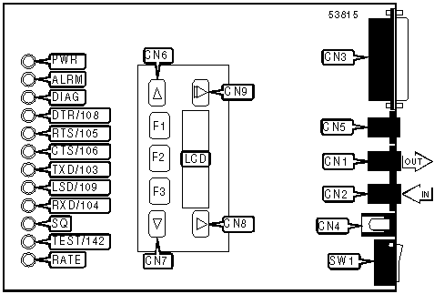
CONNECTIONS | ||||
Purpose | Location | Purpose | Location | |
Line out | CN1 | Scroll left on LCD | CN6 | |
Line in | CN2 | Scroll right on LCD | CN7 | |
RS-232/422 | CN3 | Up one level on LCD | CN8 | |
DC power | CN4 | Go to top level on LCD | CN9 | |
Network Management System | CN5 | Power switch | SW1 | |
DIAGNOSTIC LED(S) | |||
LED | Color | Status | Condition |
PWR | Green | On | Power is on |
PWR | Green | Off | Power is off |
ALRM | Red | Blinking | Internal malfunction detected |
ALRM | Red | Off | Normal operation |
DIAG | Green | On | Response made to network management diagnostic |
DIAG | Green | Off | No Response made to network management diagnostic |
DTR/108 | Green | On | DTR signal is high |
DTR/108 | Green | Off | DTR signal is low |
RTS/105 | Green | On | RTS signal is high |
RTS/105 | Green | Off | RTS signal is low |
CTS/106 | Green | On | CTS signal is high |
CTS/106 | Green | Off | CTS signal is low |
TXD/103 | Green | On | Modem is transmitting data |
TXD/103 | Green | Off | Modem is not transmitting data |
LSD/109 | Green | On | Carrier signal detected |
LSD/109 | Green | Off | Carrier signal not detected |
RXD/104 | Green | On | Modem is receiving data |
RXD/104 | Green | Off | Modem is not receiving data |
SQ | Yellow | On | Incoming signal is degraded |
SQ | Yellow | Off | Normal operation |
TEST/142 | Yellow | On | Test in progress. Halt operation. |
TEST/142 | Yellow | Off | Normal operation |
RATE | Yellow | On | Modem connected at less than configured speed |
RATE | Yellow | Off | Modem connected at configured speed |
Proprietary AT Command Set
AT COMMAND RESPONSE | |
Type: | Register |
Format: | AT [cmds] S84=n [cmds] |
Example: | AT S84=0 &W <CR> |
Description: | Sets the response to AT commands. |
Command | Function |
í S84=0 | Normal operation |
S84=1 | Execute valid commands, suppress error codes. |
S84=2 | Ignore configuration commands, always return OK error code. |
AUTODIAL STANDBY | |
Type: | Register |
Format: | AT [cmds] S47=n [cmds] |
Example: | AT S47=0 &W <CR> |
Description: | Selects length of wait before modem autodials in dial backup mode. |
Command | Function |
í S47=0 | Disabled |
S47=1 | 15 minutes |
S47=2 | 1 hour |
S47=3 | 4 hours |
S47=255 | Test 2 minutes |
AUTO REDIAL | |
Type: | Register |
Format: | AT [cmds] S37=n [cmds] |
Example: | ATS37=6 <CR> |
Default: | Unidentified. |
Unit: | 1 stored number. |
Description: | Redial from a list of stored numbers |
Command | Function |
S36=0 | Dial stored number 1 |
S36=1 | Dial stored numbers 1-2. |
S36=2 | Dial stored numbers 1-3. |
S36=3 | Dial stored numbers 1-4. |
S36=4 | Dial stored numbers 1-5. |
S36=5 | Dial stored numbers 1-6 |
S36=6 | Dial stored numbers 1-7. |
S36=7 | Dial stored numbers 1-8. |
S36=8 | Dial stored numbers 1-9. |
S36=9 | Dial stored numbers 1-10. |
AUTO-RELIABLE FALLBACK CHARACTER | |
Type: | Configuration |
Format: | AT [cmds] %An [cmds] |
Example: | AT%A20 <CR> |
Default: | 19 |
Range: | 0-127 |
Unit: | ASCII |
Description: | Sets the character used as the auto-reliable fallback character. %A0 will disable this function. |
AUTO-RELIABLE TIME BUFFER CONFIGURATION | |
Type: | Configuration |
Format: | AT [cmds] \Cn [cmds] |
Example: | AT \C1 &W <CR> |
Description: | Controls the handling of incoming data during auto-reliable time period. |
Command | Function |
\CO | Data is discarded. |
\C1 | Data is buffered. |
\C2 | Data is discarded, resets to \C1 on receipt of autoreliable fallback character. |
BREAK TYPE | |
Type: | Configuration |
Format: | AT [cmds] \Kn [cmds] |
Example: | AT \K5 &W <CR> |
Description: | Selects response to DTE break command. |
Command | Function |
\K0 | Send break, clear buffer, enter command mode. |
\K1 | Send break, clear buffer |
\K2 | Send break, send data, enter command mode. |
\K3 | Send break. send data, |
\K4 | Send data, send break, enter command mode. |
\K5 | Send data, send break. |
\K6 | Disabled. |
BUSY OUT ON LOW DTR | |
Type: | Register |
Format: | AT [cmds] S69=n [cmds] |
Example: | AT S69=0 &W <CR> |
Description: | Modem goes off hook on low DTR. |
Command | Function |
í S69=0 | Busy out disabled. |
S699=1 | Busy out enabled. |
CALLBACK STORED NUMBER | |
Type: | Register |
Format: | AT [cmds] S67=n [cmds] |
Example: | AT S67=0<CR> |
Description: | Callback function will dial the number stored in memory location 1. |
Command | Function |
í S67=0 | Disabled. |
S67=1 | Enabled. |
CELLULAR ENHANCEMENT | |
Type: | Register |
Format: | AT [cmds] S91=n [cmds] |
Example: | AT S91=0 &W <CR> |
Description: | Adjusts profile to improve cellular performance |
Command | Function |
í S91=0 | Disabled. |
S91=1 | Enabled. |
CD SIGNAL | |
Type: | Configuration |
Format: | AT [cmds] &Cn [cmds] |
Example: | AT &C3 *RS1 *SR1<CR> |
Description: | Configures the behavior of the carrier detect signal. |
Command | Function |
&C0 | CD forced high. |
í &C1 | CD normal. |
&C2 | CD forced high except during handshaking and disconnecting. |
&C3 | CD momentary interrupt on disconect. |
&C4 | CD follows remote RTS signal. |
&C5 | CD Follows DTR signal. Forced low on disconnect. |
&C6 | CD forced low on retrain of over 10 sec. Forced high after no retrain for over 10 sec. |
COMPRESSION | |
Type: | Configuration |
Format: | AT %Cn |
Example: | AT *EC0 %C1 *AP0 <CR> |
Description: | Selects data compression. |
Command | Function |
%C0 | Data compression disabled. |
í %C1 | Data compression enabled. |
CONNECT MODE | |
Type: | Configuration |
Format: | AT [cmds] \Nn [cmds] |
Example: | AT \N1 DT555-1212 <CR> |
Description: | Sets connect mode. |
Command | Function |
\N0 | Normal mode enabled. |
\N1 | Direct mode enabled. |
\N2 | MNP mode only enabled. |
\N3 | MNP mode with fallback to normal mode enabled. |
\N4 | V.42/MNP only enabled. |
\N5 | V.42/MNP with fallback to normal mode enabled. |
\N6 | LAP-M mode only enabled. |
\N7 | LAP-M mode with fallback to normal mode enabled. |
CTS SIGNAL | |
Type: | Configuration |
Format: | AT [cmds] \Dn [cmds] |
Example: | AT \D0 <CR> |
Description: | Selects the function of the CTS signal. |
Command | Function |
í \D0 | CTS forced high. |
\D1 | CTS normal. |
\D2 | CTS interrupted for 2 seconds on disconnect. |
\D3 | CTS follows DTR. |
DIAL BACKUP REPEAT | |
Type: | Register |
Format: | AT [cmds] S38=n [cmds] |
Example: | AT S38=0 &W <CR> |
Description: | Controls redial for dial backup |
Command | Function |
í S38=0 | Redial stored dial backup numbers once. |
S38=1 | Redial stored dial backup numbers continuously. |
DIAL TYPE SELECTION | |
Type: | Configuration |
Format: | AT [cmds] &Jn [cmds] |
Example: | AT &J0 D555-1212<CR> |
Description: | Selects which type of dialing will be used as default. |
Command | Function |
í &J0 | Permissive (-9dBm) |
&J1 | Programmable |
DISCONNECT BUFFER DELAY | |
Type: | Register |
Format: | AT [cmds] S39=n [cmds] |
Example: | AT S39=0 <CR> |
Default: | 0 |
Range: | 0-255 |
Unit: | 1 second |
Description: | Configures how long the modem will wait to disconnect if there is data in the transmit or receive buffers. |
DISCONNECT IMMEDIATELY | |
Type: | Register |
Format: | AT [cmds] S85=n [cmds] |
Example: | AT S85=0 &W <CR> |
Description: | Disconnect immediately on receipt of disconnect signal from DTE or diagnostic control panel. |
Command | Function |
í S85=0 | Disabled. |
S85=1 | Enabled. |
DISCONNECT INACTIVITY | |
Type: | Register |
Format: | AT [cmds] S80=n [cmds] |
Example: | AT S80=3 &W <CR> |
Description: | Sets the signal monitored by the inactivity timer (\T). |
Command | Function |
S80=0 | Transmit or receive. |
S80=1 | Transmit only. |
S80=2 | Receive only. |
í S80=3 | Transmit and receive. |
DISCONNECT ON LOSS OF CURRENT | |
Type: | Register |
Format: | AT [cmds] S65=n [cmds] |
Example: | AT S65=0 <CR> |
Description: | Causes the modem to disconnect if the telephone line’s current drops. |
Command | Function |
í S65=0 | Disconnect after 8ms if current is lost. |
S65=1 | Disconnect after 90ms if current is lost. |
S65=2 | Disabled |
DTE RATE CONTROL | |
Type: | Register |
Format: | AT [cmds] S61=n [cmds] |
Example: | AT S61= &W <CR> |
Description: | Sets result of DTE CT111 rate control signal. |
Command | Function |
í S61=0 | Disabled. |
S61=-1 | Fallback 1. |
S61=2 | Fallback 2. |
DTR ALARM | |
Type: | Register |
Format: | AT [cmds] S77=n [cmds] |
Example: | AT S77=0 &W <CR> |
Description: | Sends alarm to proprietary Series Management Controller if DTR low for 10 seconds. |
Command | Function |
í S77=0 | Alarm disabled. |
S77=1 | Alarm enabled. |
FACTORY DEFAULTS | |
Type: | Immediate/Configuration |
Format: | AT &F[n] |
Example: | AT &F0 <CR> |
Description: | Loads factory defaults to NVRAM. |
Command | Function |
&F0 | Asynchronous dial. |
&F1 | Synchronous switched line |
&F2 | Synchronous leased line answer mode |
&F3 | UNIX dial. |
&F4 | Synchronous leased line originate mode |
&F5 | Cellular (Mobile). Load \A4, \N4, S0=3, S7=120, S10=100, S43=1, S76=3, S89=9, S91=1. |
&F6 | Cellular (PSTN). Load &I100, \N4, S7=120, S10=100, S43=1, S89=9, S91=1 |
FLOW CONTROL | |
Type: | Configuration |
Format: | AT [cmds] \Gn [cmds] |
Example: | AT G1 &K3 <CR> |
Description: | Selects modem port flow control. |
Command | Function |
í \G0 | Flow control disabled. |
\G1 | Flow control enabled. |
FLOW CONTROL TYPE | |
Type: | Configuration |
Format: | AT [cmds] \Qn [cmds] |
Example: | AT \Q5 <CR> |
Description: | Sets type of flow control used by modem. |
Command | Function |
\Q0 | Flow control disabled. |
\Q1 | Bidirectional XON/XOFF flow control enabled. |
í \Q2 | CTS flow control by DCE enabled. |
\Q3 | Bidirectional CTS/RTS flow control enabled. |
\Q4 | XON/XOFF flow control by DCE enabled. |
\Q5 | XON/XOFF flow control by DTE enabled. |
\Q6 | RTS flow control by DTE enabled. |
HANDSHAKE OPTIONS | |
Type: | Register |
Format: | AT [cmds] S43=n [cmds] |
Example: | AT S43=0 <CR> |
Default: | 0 |
Range: | 0, 1 |
Description: | Controls the V.32bis handshake sequence. |
Command | Function |
í S43=0 | V.32bis long handshake. |
S43=1 | V.32is short handshake. |
INACTIVITY TIMER | |
Type: | Configuration |
Format: | AT [cmds] \Tn [cmds] |
Example: | AT\T20 <CR> |
Default: | 0 |
Range: | 0-255 |
Unit: | 1 second |
Description: | Sets the length of time that the modem does not receive information before it disconnects. |
LAP-M FRAME SIZE4 | |
Type: | Configuration |
Format: | AT [cmds] \An [cmds] |
Example: | AT \A3 %C1 <CR> |
Description: | Sets the maximum frame size for V.42 and MNP connections. |
Command | Function |
\A0 | Maximum frame size is 64 |
\A1 | Maximum frame size is 128 |
\A2 | Maximum frame size is 192 |
\A3 | Maximum frame size is 256 |
\A4 | Maximum frame size is 32 |
\A5 | Maximum frame size is 16 |
Note: Maximum V.42 frame size is 128. | |
LAP-M FRAME WINDOW | |
Type: | Register |
Format: | AT [cmds] S89=n [cmds] |
Example: | ATS89=6 <CR> |
Default: | 0 |
Range: | 1-9 |
Unit: | 1 frame (beginning with 0=6 frames) |
Description: | Sets the number of frames used in V.42 and V.42bis transmissions |
LEASED LINE AUTO-RETRAIN | |
Type: | Register |
Format: | AT [cmds] S82=n [cmds] |
Example: | AT S82=0 &W <CR> |
Description: | Allows modem to retrain to compensate for bad line quality. |
Command | Function |
í S82=0 | Retrain enabled. |
S82= | Retrain disabled. |
LEASED LINE SPEED | |
Type: | Register |
Format: | AT [cmds] S44=n [cmds] |
Example: | ATS44=6 <CR> |
Default: | 18 |
Description: | Sets maximum leased line speed |
Command | Function |
S44=0 | 14.4Kbps V.32bis |
S44=1 | 14.4Kbps V.32bis |
S44=2 | 12.0Kbps V.32bis |
S44=3 | 9600bps V.32bis |
S44=4 | 7200bps V.32bis |
S44=5 | 4800bps V.32bis |
S44=6 | 2400bps V.22bis |
í S44=18 | 19.2Kbps V.32terbo |
S44=19 | 16.8bps V.32terbo |
LEASED LINE TRANSMISSION LEVEL | |
Type: | Register |
Format: | AT [cmds] S45=n [cmds] |
Example: | AT S45=15 <CR> |
Default: | 0 |
Range: | 0 - 15 |
Unit: | 1 dBm |
Description: | Sets the signal level for transmission when in leased line mode. |
LINE SPEED | |
Type: | Register |
Format: | AT [cmds] S41=n [cmds] |
Example: | ATS41=6 <CR> |
Default: | 20 |
Description: | Sets maximum line speed |
Command | Function |
S41=1 | 14.4Kbps V.32bis |
S41=2 | 12.0Kbps V.32bis |
S41=3 | 9600bps V.32bis, V.32 |
S41=4 | 7200bps V.32bis |
S41=5 | 4800bps V.32bis, V.32 |
S41=6 | 2400bps V.22bis |
S41=7 | 1200bps V.22 |
S41=8 | 1200bps 212A |
S41=10 | 0-300bps V21 |
S41=11 | 0-300bps 103j |
S41=12 | 1200/75bps V.23 |
S41=13 | 75/1200bps V.23 |
í S41=20 | 19.2Kbps V.32terbo |
S41=21 | 16.8bps V.32terbo |
LOCAL ANALOG LOOPBACK | |
Type: | Register |
Format: | AT [cmds] S52=n [cmds] |
Example: | AT S52=0 &W <CR> |
Description: | Modem executes local analog loopback on receipt of CT140 signal from DTE |
Command | Function |
í S52=0 | Loopback disabled. |
S52=1 | Loopback enabled. |
LOCK SERIAL PORT | |
Type: | Register |
Format: | AT [cmds] S90=n [cmds] |
Example: | AT S90=0 <CR> |
Description: | Sets operation of serial port speed. |
Command | Function |
í S90=0 | Disabled. |
S90=1 | Serial speed follows connect speed. |
MI/MIC | |
Type: | Register |
Format: | AT [cmds] S83=n [cmds] |
Example: | AT S83=0 &W <CR> |
Description: | Configures the Mode Indicate/Mode Indicate Common (MI/MIC) interface. |
Command | Function |
í S83=0 | Disabled. |
S83=1 | Enabled. |
PASSWORD REMOTE ACCESS | |
Type: | Register |
Format: | AT [cmds] S56=n [cmds] |
Example: | ATS56=6 <CR> |
Default: | None |
Range: | 00-99 |
Unit: | Password digits |
Description: | Allows entry of the first two digits of remote access password. |
PASSWORD REMOTE ACCESS | |
Type: | Register |
Format: | AT [cmds] S57=n [cmds] |
Example: | ATS57=6 <CR> |
Default: | None |
Range: | 00-99 |
Unit: | Password digits |
Description: | Allows entry of the second two digits of remote access password. |
PASSWORD REMOTE ACCESS | |
Type: | Register |
Format: | AT [cmds] S58=n [cmds] |
Example: | ATS58=6 <CR> |
Default: | None |
Range: | 00-99 |
Unit: | Password digits |
Description: | Allows entry of the third two digits of remote access password. |
PASSWORD REMOTE ACCESS | |
Type: | Register |
Format: | AT [cmds] S59=n [cmds] |
Example: | ATS59=6 <CR> |
Default: | None |
Range: | 00-99 |
Unit: | P4assword digits |
Description: | Allows entry of the fourth two digits of remote access password. |
REMOTE CONFIGURATION | |
Type: | Register |
Format: | AT [cmds] S55=n [cmds] |
Example: | AT S55=0 &W <CR> |
Description: | Allows remote configuration by 3800 series modem. |
Command | Function |
í S55=0 | Remote configuration enabled. |
S55=1 | Remote configuration disabled. |
REMOTE DIGITAL LOOPBACK | |
Type: | Register |
Format: | AT [cmds] S51=n [cmds] |
Example: | AT S51=0 &W <CR> |
Description: | Modem executes remote digital loopback on receipt of CT140 signal from DTE |
Command | Function |
í S51=0 | Loopback disabled. |
S51=1 | Loopback enabled. |
REPORT INFORMATION | |
Type: | Immediate |
Format: | AT [cmds] In [cmds] |
Example: | AT I1 O <CR> |
Description: | Displays modem properties. |
Command | Function |
I0 | Display product code. |
I1 | Display 3 digit firmware revision number. |
I2 | Reports current EPROM checksum. |
I3 | Display serial number. |
I4 | Display model number. |
I5 | Display hardware part number. |
I6 | Display firmware release number. |
I9 | Display 3 digit firmware revision number. |
I10 | Changes value displayed by I0 |
I10=0 | Display 144 |
I10=1 | Display 240 |
I10=2 | Display 480 |
I10=3 | Display 960 |
I10=4 | Display 120 |
I11 | Reports RAM checksum result. |
!19 | Display complete firmware revision number. |
RESET MODEM TO STORED PROFILE | |
Type: | Configuration |
Format: | AT [cmds] Zn [cmds] |
Example: | AT Z0 <CR> |
Description: | Restores modem profiles previously saved in non-volatile RAM using the &W command. |
Command | Function |
Z0 | Restore profile 0. |
Z1 | Restore profile 1. |
Z2 | Restore profile 2. |
Z3 | Restore profile 3. |
Z9 | Restore factory defaults and use them as power-on defaults. |
RESULT CODES | |
Type: | Configuration |
Format: | AT [cmds] Xn [cmds] |
Example: | AT X5 &W <CR> |
Description: | Enables extended result codes, EC and V.42, MNP suffix, dial tone and busy signal detect |
Command | Function |
X0 | Disabled. |
X1 | Enable extended result codes. |
X2 | Enable extended result codes and dial tone detect. |
X3 | Enable extended result codes and busy signal detect |
í X4 | Enable extended result codes, dial tone detect and busy signal detect |
X5 | Enable extended result codes, EC suffix, dial tone detect and busy signal detect |
X6 | Enable extended result codes, V.42, MNP suffix, dial tone detect and busy signal detect |
X7 | Display DTE rate. Enable dial tone detect and busy signal detect |
RJ11 CELLULAR ADAPT | |
Type: | Register |
Format: | AT [cmds] S93=n [cmds] |
Example: | AT S93=0 &W <CR> |
Description: | Adds support for RJ11 connection during cellular operation |
Command | Function |
í S93=0 | Disabled. |
S93=1 | Enabled. |
STORED PROFILE | |
Type: | Register |
Format: | AT [cmds] S88=n [cmds] |
Example: | AT S88=0 &W <CR> |
Description: | Loads stored profile on disconnect. |
Command | Function |
í S88=0 | Disabled. |
S88=231 | Disabled. |
S88=1 | Enabled. |
S88=232 | Enabled. |
TRANSMISSION LEVEL | |
Type: | Configuration |
Format: | AT [cmds] &In [cmds] |
Example: | AT &I26 &W <CR> |
Default: | 0 |
Range: | 10-32, 99, 100 |
Unit: | -1 dBm |
Description: | Sets the signal level for transmission |
Note: Set to 99 for autoadjust ETC1.0 specification. Set to 100 for autoadjust ETC1.1 specifucation | |
V.25bis CODE SET | |
Type: | Register |
Format: | AT [cmds] S62=n [cmds] |
Example: | AT S62=0 &W <CR> |
Description: | Sets coding type used in V.25bis mode. |
Command | Function |
í S62=0 | ASCII |
S62=1 | EBCDIC |
V.25bis NEW LINE CHARACTER | |
Type: | Register |
Format: | AT [cmds] S64=n [cmds] |
Example: | AT S64=0 &W <CR> |
Description: | Sets V.25 new line character. |
Command | Function |
í S64=0 | Carriage return and line feed. |
S64=1 | Carriage return. |
S64=2 | Line feed. |
V.32bis AUTO-RETRAIN | |
Type: | Register |
Format: | AT [cmds] S76=n [cmds] |
Example: | AT S76=0 &W <CR> |
Description: | Selects action the modem will take during bad line quality on 32bis connection. |
Command | Function |
í S76=0 | Auto retrain enabled. |
S76=1 | Auto retrain disabled. |
S76=2 | Auto retrain started at 4800bps. |
S76=3 | Auto retrain started at 9600bps |
V.32bis/PBX AUTOMODE | |
Type: | Register |
Format: | AT [cmds] S78=n [cmds] |
Example: | AT S78=0 &W <CR> |
Description: | Selects allowed modulations. |
Command | Function |
í S78=0 | Use any supported modulation. |
S78=1 | Use modulation specified in S41 |
S78=2 | Use PBX modulation. |
V.42bis COMPRESSION CONTROL | |
Type: | Configuration |
Format: | AT [cmds] "Hn [cmds] |
Example: | AT "H3 &W <CR> |
Description: | Controls V.42bis data compression |
Command | Function |
"H0 | V.42bis disabled. |
"H1 | V.42bis when transmitting enabled. |
"H2 | V.42bis when receiving enabled. |
í "H3 | V.42bis when transmitting/receiving enabled. |
V.54 ADDRESS | |
Type: | Register |
Format: | AT [cmds] S53=n [cmds] |
Example: | ATS53=6 <CR> |
Default: | 0 |
Range: | 0-34 |
Unit: | Address of modem. 0 is disable. |
Description: | Identifies modem in loopback test. |
V.54 DEVICE TYPE | |
Type: | Register |
Format: | AT [cmds] S54n [cmds] |
Example: | AT S54=0 &W <CR> |
Description: | Identifies modem’s network position. |
Command | Function |
í S54=0 | Peripheral |
S54=1 | Intermediate |
XON/XOFF PASS-THROUGH | |
Type: | Configuration |
Format: | AT [cmds] \Xn [cmds] |
Example: | AT \X7 O <CR> |
Description: | Selects whether XON/XOFF signals are sent to remote modem. |
Command | Function |
í \X0 | XON/XOFF signals trapped by local modem. |
\X1 | XON/XOFF passed through local modem. |


My Books

