


ARTEMUX-25 SCSA modem/telephone/ISDN Settings and Configuration
IML, INC.
ARTEMUX-25 SCSA
Card Type | Telephony/Network |
NIC Type | ATM |
I/O Options | MVIP bus |
Network Transfer Rate | Unidentified |
Data Bus | 32-bit PCI |
Topology | Star |
Wire Type | Unshielded twisted pair |
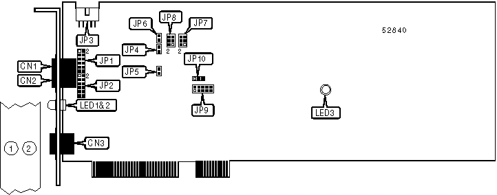
CONNECTIONS | |||
Function | Label | Function | Label |
Line 1 out | CN1 | ATM connector | CN3 |
Line 2 out | CN2 | DC power in | JP3 |
Note:This card requires an external DC power supply to be connected to JP3. For more information, contact the manufacturer. | |||
USER CONFIGURABLE SETTINGS | |||
Setting | Label | Position | |
Line 1 audio output fed through to audio input | JP4 | Closed | |
Line 1 audio output not fed through to audio input | JP4 | Open | |
Line 2 audio output fed through to audio input | JP5 | Closed | |
Line 2 audio output not fed through to audio input | JP5 | Open | |
| » | Factory configured - do not alter | JP6 | Pins 1 & 2 closed |
| » | Factory configured - do not alter | JP10 | Pins 2 & 3 closed |
LINE 1 CONFIGURATION | ||
Setting | JP1 | JP7 |
Subscriber Line Interface Circuit | Pins 5 & 6, 7 & 8 closed | Pins 3 & 5, 4 & 6 closed |
Telephone handset | Pins 1 & 2, 3 & 5, 7 & 9, 11 & 12 closed | Pins 1 & 3, 2 & 4 closed |
LINE 2 CONFIGURATION | ||
Setting | JP2 | JP8 |
Central Office Interface Circuit | Pins 5 & 6, 7 & 8 closed | Pins 3 & 5, 4 & 6 closed |
Telephone handset | Pins 1 & 2, 3 & 5, 7 & 9, 11 & 12 closed | Pins 1 & 3, 2 & 4 closed |
DIAGNOSTIC LED(S) | |||
LED | Color | Status | Condition |
LED1 | Green | On | ATM is transmitting a cell |
LED1 | Green | Off | ATM is not transmitting a cell |
LED2 | Green | On | ATM is receiving a cell |
LED2 | Green | Off | ATM is not receiving a cell |
LED3 | Red | On | On-board CPU halted |
LED3 | Red | Off | On-board CPU operation normal |
Note:The exact location of LED3 is unidentified. However, it is in the vicinity of its location on the diagram. | |||


My Books

