HM 18022 modem/telephone/ISDN Settings and Configuration
HARMONY MULTIMEDIA
HM 18022
Card Type | Modem (asynchronous) |
Chip Set | TI |
I/O Options | Audio line in, speaker out, microphone, line in, line out |
Maximum Modem Rate | 56.0Kbps |
Maximum Fax Rate | 14.4Kbps |
Data Modulation Protocol | Bell 103/212A ITU-T V.21, V.22, V.22bis, V.23, V.32, V.32bis, V.34, x2 |
Fax Modulation Protocol | ITU-T V.17, V.27ter, V.29 |
Error Correction/Compression | MNP5, V.42, V.42bis |
Fax Class | Class I |
Data Bus | 16-bit ISA |
Card Size | Half-length, full-height card |
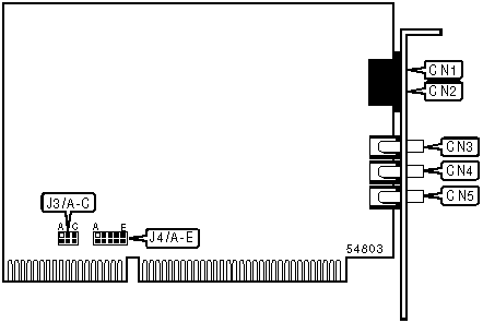
CONNECTIONS | ||||||
Function | Label | Function | Label | |||
Line in | CN1 | Speaker out | CN4 | |||
Line out | CN2 | Microphone | CN5 | |||
Audio line in | CN3 | |||||
SERIAL PORT ADDRESS | |||
Setting | J3/A | J3/B | J3/C |
COM1 (3F8h) | Closed | Closed | Closed |
COM2 (2F8h) | Open | Closed | Closed |
COM3 (3E8h) | Closed | Open | Closed |
COM4 (2E8h) | Open | Open | Closed |
Plug & Play | Open | Open | Open |
INTERRUPT | |||||
Setting | J4/A | J4/B | J4/C | J4/D | J4/E |
IRQ 2 | Closed | Open | Open | Open | Open |
IRQ 3 | Open | Closed | Open | Open | Open |
IRQ 4 | Open | Open | Closed | Open | Open |
IRQ 5 | Open | Open | Open | Closed | Open |
IRQ 7 | Open | Open | Open | Open | Closed |
SUPPORTED COMMAND SET |
Basic AT Commands |
AT, ‘+++’ A/ |
A, B, D, E, F, H, M, O, V, X |
&C, &G, &R, &T, &Z |
S Registers |
S0, S1, S2, S3, S4, S5, S6, S7, S8, S9, S10, S11, S12, S18, S25 |
Note: See MHI Help File for full command documentation. |
Proprietary AT Command Set
DISPLAY COMMANDS | |
Type: | Configuration |
Format: | AT [cmds] $ [cmds] |
Description: | Display a list of commands |
Note: The $ command can be used with all prefixes. | |
SPEAKER VOLUME | |
Type: | Configuration |
Format: | AT [cmds] Ln [cmds] |
Description: | Controls speaker volume |
Command | Function |
L0 | Low volume setting |
L1 | Low volume setting |
í L2 | Medium volume setting |
L3 | Highest volume setting |
RESULT CODES | |
Type: | Configuration |
Format: | AT [cmds] Qn [cmds] |
Description: | Enables modem to send result codes to the DTE |
Command | Function |
í Q0 | Result code sending enabled |
Q1 | Result code sending disabled |
Q2 | Display result codes only in Originate mode |
Q3 | Display result codes only in Ring mode |
DEFAULT CONFIGURATION | |
Type: | Configuration |
Format: | AT [cmds] Yn [cmds] |
Description: | Set power on/reset default configuration |
Command | Function |
í Y0 | Profile 0 |
Y1 | Profile 1 |
Y2 | Generic Template (&F0) |
Y3 | Hardware flow control (&F1) |
Y4 | Software flow control (&F2) |
SOFT RESET | |
Type: | Immediate |
Format: | AT [cmds] Zn [cmds] |
Description: | Restores modem profiles previously saved in non-volatile RAM using the &W command. |
Command | Function |
Z0 | Resets modem to NVRAM profile selected by Y command |
Z1 | Resets modem to NVRAM profile 0 |
Z2 | Resets modem to NVRAM profile 1 |
Z3 | Resets modem to factory default profile 0 |
Z4 | Resets modem to factory default profile 1 |
Z5 | Resets modem to factory default profile 2 |
MODIFY RESPONSES | |
Type: | Configuration |
Format: | AT [cmds] &An [cmds] |
Description: | Selects the modify responses |
Command | Function |
í &A0 | ARQ result codes disabled |
&A1 | Append/ARQ to word CONNECT responses when an error-correction connection is made |
&A2 | Append additional V.32 indicator in result codes for calls at or above 4800bps |
&A3 | Append Protocol of call: /LAPM, /MNP or NONE and V.42bis/MNP5 |
DTE INTERFACE SPEED | |
Type: | Configuration |
Format: | AT [cmds] &Bn [cmds] |
Description: | Controls the DTE interface speed |
Command | Function |
í &B0 | Serial speed follows connect speed |
&B1 | Serial speed locked |
&B2 | In answer mode, fix serial port speed for ARQ calls and change it for non-ARQ calls |
DATA TERMINAL READY (DTR) | |
Type: | Configuration |
Format: | AT [cmds] &Dn [cmds] |
Description: | Selects modem response to DTR |
Note: The action each variant of &D causes depends on the setting of &Q | |
Command | Function |
í &D0 | Modem does not respond to DTR |
&D1 | Modem goes to command mode after DTR goes is off |
&D2 | Modem goes to command mode and disconnects (hangs up) after DTR goes off; Auto-Answer is disabled. |
FACTORY DEFAULT PROFILE | |
Type: | Configuration |
Format: | AT [cmds] &F [cmds] |
Description: | Sets values in active profile to values found in the default profile |
Command | Function |
í &F0 | Restore factory configuration: X1 &A1, &B0, &I0, &R1 |
&F1 | Restore factory profile 1 (hardware flow control) |
&F2 | Restore factory profile 2 (software flow control) |
FLOW CONTROL | |
Type: | Configuration |
Format: | AT [cmds] &Hn [cmds] |
Description: | Sets the flow control |
Command | Function |
í &H0 | Flow control disabled |
&H1 | Hardware flow control enabled |
&H2 | Software flow control enabled |
&H3 | Hardware and software flow control enabled |
XON/XOFF FLOW CONTROL | |
Type: | Configuration |
Format: | AT [cmds] &In [cmds] |
Description: | Sets the XON/XOFF flow control pass through |
Command | Function |
í &I0 | XON/XOFF flow control disabled |
&I1 | XON/XOFF signals processed to modem and remote system |
&I2 | XON/XOFF signals processed to modem only |
DATA COMPRESSION | |
Type: | Configuration |
Format: | AT [cmds] &Kn [cmds] |
Description: | Controls the V.42bis and MNP Class 5 data compression |
Command | Function |
&K0 | Data compression disabled |
&K1 | Data compression enabled if the DTE data rate is higher than the link rate and the remote DCE either supports MNP 5 of V.42bis |
&K2 | Data compression enabled |
&K3 | V.42bis data compression only |
OPERATING MODE | |
Type: | Configuration |
Format: | AT [cmds] &Mn [cmds] |
Description: | Selects operating mode |
Command | Mode |
&M0 | Normal mode |
í &M4 | Auto-reliable mode |
&M5 | MNP reliable mode |
DCE LINK RATE | |
Type: | Configuration |
Format: | AT [cmds] &Nn [cmds] |
Description: | Selects the DCE link rate |
Command | Function |
í &N0 | Variable rate |
&N1 | Attempt at 300bps connection |
&N2 | Attempt at 1200bps connection |
&N3 | Attempt at 2400bps connection |
&N4 | Attempt at 4800bps connection |
&N5 | Attempt at 7200bps connection |
&N6 | Attempt at 9600bps connection |
&N7 | Attempt at 12000bps connection |
&N8 | Attempt at 14400bps connection |
&N9 | Attempt at 16800bps connection |
&N10 | Attempt at 19200bps connection |
&N11 | Attempt at 21600bps connection |
&N12 | Attempt at 24000bps connection |
&N13 | Attempt at 26400bps connection |
&N14 | Attempt at 28800bps connection |
&N15 | Attempt at 31200bps connection |
&N16 | Attempt at 33600bps connection |
&N17 | Attempt at 32000bps connection |
&N18 | Attempt at 36000bps connection |
&N19 | Attempt at 40000bps connection |
&N20 | Attempt at 44000bps connection |
&N21 | Attempt at 48000bps connection |
&N22 | Attempt at 49333bps connection |
&N23 | Attempt at 50666bps connection |
&N24 | Attempt at 52000bps connection |
PULSE RATIO | |
Type: | Configuration |
Format: | AT [cmds] &Pn [cmds] |
Description: | Selects the pulse make/break ratio |
Command | Mode |
í &P0 | 39/61ms at 10pps (North America) |
&P1 | 33/67ms at 10pps (Europe) |
DATA SET READY (DSR) | |
Type: | Configuration |
Format: | AT [cmds] &Sn [cmds] |
Description: | Selects DSR options |
Command | Function |
&S0 | DSR forced high |
í &S1 | DSR high only while modem is handshaking or connected |
DCE LINK FLOOR | |
Type: | Immediate |
Format: | AT [cmds] &Un |
Description: | Selects the DCE link rate floor |
Command | Function |
&U0 | Disable |
&U1 | 300bps |
&U2 | 1200bps |
&U3 | 2400bps |
&U4 | 4800bps |
&U5 | 7200bps |
&U6 | 9600bps |
&U7 | 12000bps |
&U8 | 14400bps |
&U9 | 16800bps |
&U10 | 19200bps |
&U11 | 21600bps |
&U12 | 24000bps |
&U13 | 26400bps |
&U14 | 28800bps |
&U15 | 31200bps |
&U16 | 33600bps |
&U17 | 32000bps |
&U18 | 36000bps |
&U19 | 40000bps |
&U20 | 44000bps |
&U21 | 48000bps |
&U22 | 49333bps |
&U23 | 50666bps |
&U24 | 52000bps |
STORE ACTIVE PROFILE | |
Type: | Configuration |
Format: | AT [cmds] &Wn [cmds] |
Description: | Writes the values for the active profile into the non-volatile RAM |
Command | Function |
&W0 | Write the S-register values to profile 0 |
&W1 | Write the S-register values to profile 1 |
BREAK HANDLING | |
Type: | Configuration |
Format: | AT [cmds] &Yn [cmds] |
Description: | Controls the break handling |
Command | Function |
í &Y0 | Destructive break |
&Y1 | Expedited destructive option |
&Y2 | Expedited non-destructive option |
S(status) -REGISTERS
INACTIVITY TIME | |
Type: | Register |
Format | AT [cmds] S19n [cmds] |
Default: | 0 |
Range: | 0-255 |
Unit: | 1 second |
Description: | Sets the maximum duration for inactivity timer |
BIT-MAPPED REGISTER S21 | |
Format | AT [cmds] S21=n [cmds] |
Default: | 10 |
Range: | 0-255 |
Unit: | .01 second |
Description: | Sets the break length character |
FLOW CONTROL CHARACTER – XON | |
Type: | Register |
Format: | AT [cmds] S22=n [cmds] |
Default: | 19 |
Range: | 0-127 |
Unit: | ASCII |
Description: | Sets the character used to represent XON |
FLOW CONTROL CHARACTER - XOFF | |
Type: | Register |
Format: | AT [cmds] S23=n [cmds] |
Default: | 19 |
Range: | 0-127 |
Unit: | ASCII |
Description: | Sets the character used to represent XOFF |
My Books

