TELEPATH WITH X2 TECHNOLOGY modem/telephone/ISDN Settings and Configuration
GATEWAY 2000
TELEPATH WITH X2 TECHNOLOGY
Card Type | Modem |
Chip Set | Unidentified |
I/O Options | Soundcard connector, serial ports (2 RJ-11), microphone jack, line in |
Maximum Modem Rate | 56Kbps |
Maximum Fax Rate | 14.4Kbps |
Data Modulation Protocol | Bell 103A/212A, ITU-T V.21, V.22, V.22bis,V.32, V.32bis, V.34, V.FC |
Fax Modulation Protocol | V.17, V.21, CH2, V.27ter, V.29 |
Error Correction/Compression | MNP5, V.42, V.42bis |
Fax Class | Class I & II |
Data Bus | 8-bit ISA |
Card Size | Half-length |
CONNECTIONS | ||||||
Function | Label | Function | Label | |||
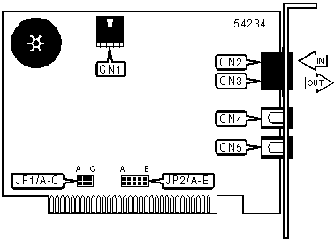
Cable connector to sound card | CN1 | Microphone jack | CN4 | |||
RJ-11 telephone in | CN2 | Line out | CN5 | |||
RJ-11 telephone out | CN3 | |||||
SERIAL PORT ADDRESS | |||
Setting | JP1/A | JP1/B | JP1/C |
COM1 (3F8h) | Closed | Closed | Closed |
í COM2 (2F8h) | Open | Closed | Closed |
COM3 (3E8h) | Closed | Open | Closed |
COM4 (2E8h) | Open | Open | Closed |
INTERRUPT | |||||
Setting | JP2/A | JP2/B | JP2/C | JP2/D | JP2/E |
IRQ2 | Closed | Open | Open | Open | Open |
í IRQ3 | Open | Closed | Open | Open | Open |
IRQ4 | Open | Open | Closed | Open | Open |
IRQ5 | Open | Open | Open | Closed | Open |
IRQ7 | Open | Open | Open | Open | Closed |
MISCELLANEOUS TECHNICAL NOTES |
A compatible sound card is necessary in order for the Speakerphone functions to operate properly. |
SUPPORTED COMMAND SET |
Basic AT Commands |
AT, ‘+++’, ‘comma’, A/ |
A, B, E, F, H, M, O, P, R, T, V, X |
&C, &G, &P, &T,&X, &Z |
S Registers |
S0, S1, S2, S3, S4, S5, S6, S7, S8, S9, S10, S11, S12, S18, S38 |
Special Commands |
#CID |
Note: See MHI Help File for full command documentation. |
PROPRIETARY AT COMMAND SET
DIAL | |
Type: | Immediate |
Format: | AT [cmds] D<#> [cmds] |
Description: | Dials telephone number according to any modifiers included in the string |
Note: | Any combination of modifiers can be used to produce the desired dial functions in sequence. |
Command | Function |
DL | Re-dial last number |
DP | Pulse dialing enabled |
DR | Answer mode enabled; originate mode disabled following handshake initiation. |
DS=n | Dial stored telephone number n |
DT | Tone dialing enabled/Pulse dialing disabled |
DW | Dialing resumed following dial tone detection |
D, | Dialing paused for amount of time specified in S8 register |
D! | Flash function initiated. Modem commanded to go off-hook for specified time before returning on-hook. |
D@ | Wait for Quite Answer function enabled. Modem waits until a "quiet answer," a ring-back signal followed by silence up to the time specified in S7, is received prior to executing the rest of the dial string. |
D$ | Displays a list of dial commands |
D; | Modem returned to idle state after dialing. The semicolon can only be placed at the end of the dial command. |
D/ | Delays for 125 msec before proceeding with dial string |
D# | Extended touch tone pad tones |
D* | Extended touch tone pad tones |
REPORT INFORMATION | |
Type: | Immediate |
Format: | AT [cmds] In [cmds] |
Description: | Displays information requested |
Command | Function |
I0 | Reports four digit product code |
I1 | Reports ROM checksum |
I2 | Reports RAM checksum |
I3 | Reports product type |
I4 | Reports current modem settings |
I5 | Reports nonvolatile memory settings |
I6 | Reports link diagnostics |
I7 | Reports product configuration |
I11 | Reports link diagnostics |
SPEAKER VOLUME | |
Type: | Configuration |
Format: | AT [cmds] Ln [cmds] |
Description: | Controls speaker volume |
Command | Function |
L0 | Low volume setting |
L1 | Low volume setting |
L2 | Medium volume setting |
L3 | Highest volume setting |
RESULT CODES | |
Type: | Configuration |
Format: | AT [cmds] Qn [cmds] |
Description: | Enables modem to send result codes to the DTE |
Command | Function |
Q0 | Result code sending enabled |
Q1 | Result code sending disabled |
Q2 | Result code sending enabled only in Originate mode |
POWER ON/RESET | |
Type: | Configuration |
Format: | AT [cmds] Yn [cmds] |
Description: | Selects power on/reset default configuration |
Command | Function |
Y0 | Profile 0 in NVRAM |
Y1 | Profile 0 in NVRAM |
Y2 | Generic template (&F0) |
Y3 | Hardware flow control (&F1) |
Y4 | Software flow control (&F2) |
SOFT RESET | |
Type: | Immediate |
Format: | AT [cmds] Zn [cmds] |
Description: | Restores modem profiles previously saved in non-volatile RAM using the &W command. |
Command | Function |
Z0 | Restore modem to profile selected by Y command |
Z1 | Restore NVRAM setting 0 |
Z2 | Restore NVRAM setting 1 |
Z3 | Resets modem to factory default profile 0 (&F0) |
Z4 | Resets modem to factory default profile 1 (&F1) |
Z5 | Resets modem to factory default profile 2 (&F2) |
CODE SUBSET DISPLAY | |
Type: | Configuration |
Format: | AT [cmds] &An [cmds] |
Description: | Enable or suppress the display of an additional result code subsets. |
Command | Function |
&A0 | Do not display ARQ result codes |
&A1 | Display ARQ result codes |
&A2 | Display modulation indicators |
&A3 | Display error control |
SERIAL PORT RATE | |
Type: | Configuration |
Format: | AT [cmds] &Bn [cmds] |
Description: | Sets serial port rate. |
&B0 | Variable, follows connection rate |
&B1 | Fixed serial port rate |
&B2 | Fixed in ARQ mode. Variable in non-ARQ mode |
DTR OPERATIONS | |
Type: | Configuration |
Format: | AT [cmds] &Dn [cmds] |
Description: | Controls Data Terminal Ready operations. |
&D0 | DTR override |
&D1 | DTR toggle case causes online command mode |
&D2 | Normal DTR operations |
FACTORY DEFAULT PROFILE | |
Type: | Configuration |
Format: | AT [cmds] &F [cmds] |
Description: | Sets values in active profile to values found in the default profile |
&F0 | Generic template |
&F1 | Hardware flow control template |
&F2 | Software flow control template |
TRANSMIT DATA FLOW CONTROL | |
Type: | Configuration |
Format: | AT [cmds] &H [cmds] |
Description: | Sets transmit data flow |
&H0 | Flow control disabled |
&H1 | Hardware flow control, CTS |
&H2 | Software flow control, XON/XOFF |
&H3 | Hardware and software flow control |
RECEIVE DATA FLOW CONTROL | |
Type: | Configuration |
Format: | AT [cmds] &I [cmds] |
Description: | Sets transmit data flow |
&I0 | Software flow control disabled |
&I1 | XON/XOFF signals to your modem and remote system |
&I2 | XON/XOFF signals to your modem only |
DATA COMPRESSION | |
Type: | Configuration |
Format: | AT [cmds] &Kn [cmds] |
Description: | Enables/disables data compression |
Command | Function |
&K0 | Data compression disabled |
&K1 | Auto enable/disable |
&K2 | Data compression enabled |
&K3 | MNP5 compression disabled |
ERROR CONTROL | |
Type: | Configuration |
Format: | AT [cmds] &Mn [cmds] |
Description: | Selects error control 1200bps and higher |
Command | Mode |
&M0 | Normal mode, error control disabled |
&M4 | Normal/ARQ |
&M5 | ARQ mode |
CONNECTION SPEED UPPER LIMIT | |
Type: | Configuration |
Format: | AT [cmds] &Nn [cmds] |
Description: | Sets required connection speed if &U is set to 0; otherwise, sets fastest allowed connection speed. |
Command | Function |
&N0 | No maximum connect speed. |
&N1 | Set maximum connect speed to 300bps. |
&N2 | Set maximum connect speed to 1200bps. |
&N3 | Set maximum connect speed to 2400bps. |
&N4 | Set maximum connect speed to 4800bps. |
&N5 | Set maximum connect speed to 7200bps. |
&N6 | Set maximum connect speed to 9600bps. |
&N7 | Set maximum connect speed to 12Kbps. |
&N8 | Set maximum connect speed to 14.4Kbps. |
&N9 | Set maximum connect speed to 16.8Kbps. |
&N10 | Set maximum connect speed to 19.2Kbps. |
&N11 | Set maximum connect speed to 21.6Kbps. |
&N12 | Set maximum connect speed to 24Kbps. |
&N13 | Set maximum connect speed to 26.4Kbps. |
&N14 | Set maximum connect speed to 28.8Kbps. |
&N15 | Set maximum connect speed to 31.2Kbps. |
&N16 | Set maximum connect speed to 33.6Kbps. |
&N17 | Set maximum connect speed to 33.3Kbps. |
&N18 | Set maximum connect speed to 37.3Kbps. |
&N19 | Set maximum connect speed to 41.3Kbps. |
&N20 | Set maximum connect speed to 42.6Kbps. |
&N21 | Set maximum connect speed to 44Kbps. |
&N22 | Set maximum connect speed to 45.3Kbps. |
&N23 | Set maximum connect speed to 46.6Kbps. |
&N24 | Set maximum connect speed to 48Kbps. |
&N25 | Set maximum connect speed to 49.3Kbps. |
&N26 | Set maximum connect speed to 50.6Kbps. |
&N27 | Set maximum connect speed to 52Kbps. |
&N28 | Set maximum connect speed to 53.3Kbps. |
&N29 | Set maximum connect speed to 56Kbps. |
&N30 | Set maximum connect speed to 57.3Kbps. |
RTS/CTS | |
Type: | Configuration |
Format: | AT [cmds] &Rn [cmds] |
Description: | Selects RTS/CTS options |
Command | Function |
&R0 | Reserved |
&R1 | RTS is ignored by modem. |
&R2 | Received data only on RTS. Controls DSR operations |
CONNECTION SPEED LOWER LIMIT | |
Type: | Configuration |
Format: | AT [cmds] &Un [cmds] |
Description: | Sets slowest allowed connection speed if &N is set to 1 or higher. |
Command | Function |
í &U0 | No minimum connect speed. |
&U1 | Set minimum connect speed to 300bps. |
&U2 | Set minimum connect speed to 1200bps. |
&U3 | Set minimum connect speed to 2400bps. |
&U4 | Set minimum connect speed to 4800bps. |
&U5 | Set minimum connect speed to 7200bps. |
&U6 | Set minimum connect speed to 9600bps. |
&U7 | Set minimum connect speed to 12Kbps. |
&U8 | Set minimum connect speed to 14.4Kbps. |
&U9 | Set minimum connect speed to 16.8Kbps. |
&U10 | Set minimum connect speed to 19.2Kbps. |
&U11 | Set minimum connect speed to 21.6Kbps. |
&U12 | Set minimum connect speed to 24Kbps. |
&U13 | Set minimum connect speed to 26.4Kbps. |
&U14 | Set minimum connect speed to 28.8Kbps. |
&U15 | Set minimum connect speed to 31.2Kbps. |
&U16 | Set minimum connect speed to 33.6Kbps. |
&U17 | Set minimum connect speed to 33.3Kbps. |
&U18 | Set minimum connect speed to 37.3Kbps. |
&U19 | Set minimum connect speed to 41.3Kbps. |
&U20 | Set minimum connect speed to 42.6Kbps. |
&U21 | Set minimum connect speed to 44Kbps. |
&U22 | Set minimum connect speed to 45.3Kbps. |
&U23 | Set minimum connect speed to 46.6Kbps. |
&U24 | Set minimum connect speed to 48Kbps. |
&U25 | Set minimum connect speed to 49.3Kbps. |
&U26 | Set minimum connect speed to 50.6Kbps. |
&U27 | Set minimum connect speed to 52Kbps. |
&U28 | Set minimum connect speed to 53.3Kbps. |
&U29 | Set minimum connect speed to 54.6Kbps. |
&U30 | Set minimum connect speed to 56Kbps. |
&U31 | Set minimum connect speed to 57.3Kbps. |
BREAK HANDLING | |
Type: | Configuration |
Format: | AT [cmds] &Yn [cmds] |
Description: | Sets break handling |
Command | Function |
&Y0 | Destructive, but doesn’t sent break |
&Y1 | Destructive, expedited |
&Y2 | Nondestructive, expedited |
&Y3 | Reserved |
S(STATUS) -REGISTERS
BIT-MAPPED REGISTER S13 | ||
Format: | AT [cmds] S13=n [cmds] | |
Range: | 0-174 | |
Unit: | Bit-mapped | |
Description: | Controls echo, result codes and display, dial mode, and answer/originate mode. | |
Bit | Value | Function |
0 | 0 1 | Unidentified Reset when DTR drops |
1 | 0 1 | Unidentified Resets non-MNP transmit buffer from 1.5K to 128bytes |
2 | 0 1 | Unidentified Set backspace key to delete |
3 | 0 1 | Unidentified DTR signals auto dial stored in NVRAM at position 0 |
4 | 0 1 | Unidentified Power on auto dial stored in NVRAM at position 0 |
5 | 0 1 | Not used Not used |
6 | 0 1 | Not used Not used |
7 | 0 1 | Unidentified Disconnect on escape code |
BIT-MAPPED REGISTER S15 | ||
Format: | AT [cmds] S15=n [cmds] | |
Range: | 0-174 | |
Description: | Bitmapped register setup. | |
Bit | Value | Function |
0 | 0 1 | Enable ARQ/MNP for V.22 Disable ARQ/MNP for V.22 |
1 | 0 1 | Enable ARQ/MNP for V.22bis Disable ARQ/MNP for V.22bis |
2 | 0 1 | Disable ARQ/MNP for V32/V.32bis Disable ARQ/MNP for V32/V.32bis |
3 | 0 1 | Enable MNP handshake Disable MNP handshake |
4 | 0 1 | Enable MNP level 4 Disable MNP level 4 |
5 | 0 1 | Enable MNP level 3 Disable MNP level 3 |
6 | 0 1 | Special MNP compatibility Special MNP incompatibility |
7 | 0 1 | Enable V.42 detection phase Disable V.42 detection phase |
TOUCH TONE DIALING TEST | ||
Format: | AT [cmds] S16=n [cmds] | |
Range: | 0-128 | |
Unit: | Bit-mapped register setup | |
Description: | Bitmapped register setup. | |
Bit | Value | Function |
1 | 0 1 | Touch tone dialing test disabled Touch tone dialing test enabled |
2 | 0 1 | Internal test pattern disabled Internal test pattern enabled |
3-6 | 0 1 | Not used Not used |
7 | 0 1 | Watchdog reset disabled Watchdog reset enabled |
INACTIVITY TIMER | |
Type: | Register |
Format | AT [cmds] S19=n [cmds] |
Default: | 0 |
Unit: | 1 minute |
Description: | Activates when there is no activity on the phone line. Modem hangs up at time-out |
Note: S19=0 disables the timer and allows an indefinite duration. | |
MNP OR V.42 MODE DELAY | |
Type: | Register |
Format | AT [cmds] S21=n [cmds] |
Range: | Unidentified |
Unit: | 10ms |
Description: | Sets the length of breaks sent from modem to computer. |
FLOW CONTROL CHARACTER - XON | |
Type: | Register |
Format: | AT [cmds] S22=n [cmds] |
Range: | Unidentified |
Unit: | ASCII |
Description: | Sets the character used to represent XON |
FLOW CONTROL CHARACTER - XOFF | |
Type: | Register |
Format: | AT [cmds] S23=n [cmds] |
Range: | Unidentified |
Unit: | ASCII |
Description: | Sets the character used to represent XOFF |
DTR DELAY | |
Format | AT [cmds] S25=n [cmds] |
Unit: | .01 second |
Description: | Selects the duration that DTR must be dropped so that the modem doesn’t interpret a random glitch as a DTR loss. |
BIT-MAPPED REGISTER S27 | ||
Format | AT [cmds] S27=n [cmds] | |
Unit: | Bit-mapped | |
Description: | Selects line modulation | |
Bit | Value | Function |
0 | 0 1 | Disables ITU-T modulation at 300bps for overseas calls; in V.21 mode, the modem answers both overseas and domestic calls but only originates V.21 calls. Enables ITU-T modulation at 300bps for overseas calls; in V.21 mode, the modem answers both overseas and domestic calls but only originates V.21 calls. |
1 | 0 1 | Disables unencoded modulation in V.32bis mode. Enables unencoded modulation in V.32bis mode |
2 | 0 1 | Enables V.32 modulation Disables V.32 modulation |
3 | 0 1 | Enables 2100Hz answer tone to allow two V.42 modems to attach more quickly Disables 2100Hz answer tone to allow two V.42 modems to attach more quickly |
4 | 0 1 | Disables V.23 fallback mode Enables V.23 fallback mode |
5 | 0 1 | Enables V.32bis mode Disables V.32bis mode |
6 | 0 1 | Not used Not used |
7 | 0 1 | Software compatibility mode disabled Software compatibility mode enabled |
ANSWER TONE DISABLE | |
Type: | Register |
Format | AT [cmds] S28=n [cmds] |
Range: | 0-255 |
Unit: | .10 second |
Description: | Eliminates the V.32 answer tones for faster dialing = "0" |
ANSWER MODE FALLBACK TIMER | |
Type: | Register |
Format | AT [cmds] S29=n [cmds] |
Range: | Undentified |
Unit: | .10 seconds |
Description: | Maximum duration of V.21/V.23 answer mode fallback timer. |
VOICE PLAYBACK AUDIO LEVEL | |
Type: | Register |
Format | AT [cmds] S31=n [cmds] |
Range: | 0-255 |
Description: | Sets voice playback audio level. |
BIT-MAPPED REGISTER S32 | |||
Format: | AT [cmds] S32=n [cmds] | ||
Range: | Unidentified | ||
Description: | Register setup for 33.6 speed modems | ||
Bit | Value | Function | |
0 | 0 1 | V.8 call indicate disabled V.8 call indicate enabled | |
1 | 0 1 | Disables V.8 mode Enables V.8 mode | |
2 | 0 1 | Enables V.FC modulation Disables V.FC modulation | |
3 | 0 1 | Enables V.34 modulation Disables V.34 modulation | |
4 | 0 1 | Enables 33.6kbps support Disables 33.6kbps support | |
5 | 0 1 | Enables X2 support Disables X2 support | |
BIT-MAPPED REGISTER S33 | |||
Format: | AT [cmds] S33=n [cmds] | ||
Description: | Register setup for 33.6 speed modems | ||
Bit | Value | Function | |
0 | 0 1 | Enables 2400 symbol rate Disables 2400 symbol rate | |
1 | 0 1 | Enables 2743 symbol rate Disables 2743 symbol rate | |
2 | 0 1 | Enables 2800 symbol rate Disables 2800 symbol rate | |
3 | 0 1 | Enables 3000 symbol rate Disables 3000 symbol rate | |
4 | 0 1 | Enables 3200 symbol rate Disables 3200 symbol rate | |
5 | 0 1 | Enables 3429 symbol rate Disables 3429 symbol rate | |
6 | 0 1 | Not used Not used | |
7 | 0 1 | Enables shaping Disables shaping | |
BIT-MAPPED REGISTER S41 | ||
Format | AT [cmds] S41=n [cmds] | |
Range: | Unidentified | |
Unit: | Bit-mapped | |
Description: | Selects ringing and speakerphone mode. | |
Bit | Value | Function |
0 | 0 1 | Distinctive ringing disabled Distinctive ringing enabled |
2,1 | 00 11 | Full Duplex speakerphone Half Duplex speakerphone mode |
VOICE COMMAND SET
MODE SELECTION | |
Type: | Immediate |
Format: | AT [cmds] #CLS=n [cmds] |
Description: | Selects which mode the modem will operate in. |
Command | Function |
#CLS=0 | Modem will operate in data mode. |
#CLS=1 | Modem will operate in fax class I mode. |
#CLS=2 | Modem will operate in fax class II mode. |
#CLS=8 | Modem will operate in voice mode. |
VOICE DEVICE | |
Type: | Configuration |
Format: | AT [cmds] #VLS=n [cmds] |
Description: | Selects the I/O device for the DSP chip. |
Note: | This modem may not support all options listed below. The #VLS? command will display the available options. |
Command | Function |
í #VLS=0 | Telephone line and handset used for voice I/O. |
#VLS=1 | Telephone handset used for voice I/O. |
#VLS=2 | Internal speaker only used for voice I/O. |
#VLS=3 | External microphone only used for voice I/O. |
#VLS=4 | Telephone line and handset used for voice I/O; internal speaker enabled. |
My Books

