ENTRE 2400B modem/telephone/ISDN Settings and Configuration
ENTRE COMPUTER CENTER
ENTRE 2400B
Modem Type | Data (asynchronous) |
Maximum Data Rate | 2400bps |
Data Bus | 8-bit ISA |
Data Modulation Protocol | Unidentified |
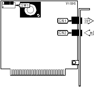
CONNECTIONS | |||
Purpose | Location | Purpose | Location |
Line out | CN1 | Line in | CN2 |
SERIAL PORT CONFIGURATION | |||
Port | IRQ | SW1/3 | SW1/4 |
| COM1: (3F8h) | 4 | On | Off |
| » COM2: (2F8h) | 3 | Off | Off |
| COM3: (3E8h) | 4 | On | On |
| COM4: (2E8h) | 3 | Off | On |
AUTO ANSWER | |
| Setting | SW1/2 |
| » Auto answer enabled | Off |
| Auto answer disabled | On |
Note: S14 holds the state of this switch at the time power turned on, or if a reset command is enabled. | |
DTR | |
| Setting | SW1/1 |
| » DTR normal | Off |
| DTR forced high | On |
CD SIGNAL | |
| Setting | SW1/5 |
| » CD normal | Off |
| CD forced high | On |
SLOT 8 INSTALLATION | |
| Setting | SW1/6 |
| » Normal installation | Off |
| IBM XT slot 8 installation | On |
Proprietary AT Command Set
BIT-MAPPED REGISTER S13 | |||
Format | AT [cmds] S13? [cmds] | ||
Example: | ATS13? <CR> | ||
Default: | Read-only | ||
Range: | 0 - 222 | ||
Unit: | Bit-mapped | ||
Description: | Displays extended result codes, parity, data bits, and buffer overrflow. | ||
Bit | Value | Function | |
0 | 0 | Not used. | |
1 | 0 1 | Extended result codes disabled. Extended result codes enabled. | |
2 | 0 1 | Parity disabled. Parity enabled. | |
3 | 0 1 | Odd parity. Even parity. | |
4 | 0 1 | 7 data bits. 8 data bits. | |
5 | N/A | Not used. | |
6 | 0 1 | Buffer is not full. Buffer overflow; ERROR result code sent. | |
7 | 0 1 | Space parity. Mark parity. | |
BIT-MAPPED REGISTER S14 | |||
Format | AT [cmds] S14? [cmds] | ||
Example: | ATS14? <CR> | ||
Default: | Read-only | ||
Range: | 0 - 239 | ||
Unit: | Bit-mapped | ||
Description: | Displays the state of SW1/2, echo, result codes, tone/pulse dial, and speaker. | ||
Bit | Value | Function | |
0 | 0 1 | SW1/2 off (Auto-answer). SW1/2 on(Auto-answer). | |
1 | 0 1 | Echo disabled. Echo enabled. | |
2 | 0 1 | Result codes enabled. Result codes disabled. | |
3 | 0 1 | Numeric result codes. Verbose result codes. | |
4 | 0 | Not used. | |
5 | 0 1 | Tone dial Pulse dial | |
6 | 0 1 | Speaker disabled Speaker enabled until carrier signal is detected. | |
7 | 0 1 | Speaker disabled. Speaker enabled. | |
BIT-MAPPED REGISTER S15 | |||
Format | AT [cmds] S15? [cmds] | ||
Example: | ATS15? <CR> | ||
Default: | Read-only | ||
Range: | 0 - 127 | ||
Unit: | Bit-mapped | ||
Description: | Displays baud rate, answer/originate, duplex, CD signal. | ||
Bit | Value | Function | |
1, 0 | 00 01 10 11 | 2400bps. 110bps. 300bps. 1200bps. | |
2 | 0 1 | Answer mode. Originate mode. | |
3 | 0 1 | Half duplex. Full duplex. | |
5, 4 | 00 01 10 11 | 2400bps. 110bps. 300bps. 1200bps. | |
6 | 0 1 | CD normal. CD forced high. | |
TEST MODES | |||
Format | AT [cmds] S16? [cmds] | ||
Example: | ATS16? <CR> | ||
Default: | Read-only | ||
Range: | 0-125 | ||
Unit: | Bit-mapped | ||
Description: | Controls loopback tests, analog, digital, remote digital, and self tests. | ||
Bit | Value | Function | |
0 | 0 1 | Local analog loopback not in progress. Local analog loopback in progress. | |
1 | 0 | Not used. | |
2 | 0 1 | Local digital loopback not in progress. Local digital loopback in progress. | |
3 | 0 1 | Modem not in remote digital loopback. Remote digital loopback in progress. | |
4 | 0 1 | Remote digital loopback not requested. Remote digital loopback requested. | |
5 | 0 1 | Remote digital loopback w/ self-test not in progress. Remote digital loopback w/ self-test in progress. | |
6 | 0 1 | Local analog loopback w/ self-test not in progress. Local analog loopback w/ self-test in progress. | |
My Books

