MICROLINK ISDN/TL PRO modem/telephone/ISDN Settings and Configuration
ELSA, INC.
MICROLINK ISDN/TL PRO
Card Type | ISDN TA |
Chip Set | Unidentified |
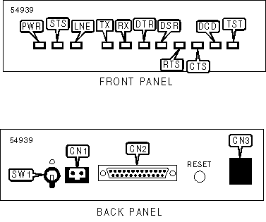
I/O Options | Power connector power switch, DTE port, ISDN interface (RJ-11) |
ISDN Data Rate | 230.4Kbps |
ISDN Modulation Protocol | V.110, V.120, X.75, PPP, T - online |
Error Correction/Compression | MNP5, V.42bis |
Data Bus | External |
CONNECTIONS | |||
Function | Label | Function | Label |
AC power connector | CN1 | ISDN interface (RJ-11 connector) | CN3 |
25-pin DTE serial port | CN2 | Power switch | SW1 |
DIAGNOSTIC LED(S) | |||
LED | Color | Status | Condition |
PWR | Unidentified | On | Power is on |
PWR | Unidentified | Off | Power is off |
STS | Unidentified | On | ISDN link is good |
STS | Unidentified | Blinking | ISDN link negotiation in progress |
STS | Unidentified | Off | ISDN link is broken |
LNE | Unidentified | On | Connection is being established |
LNE | Unidentified | Blinking (slow) | Incoming call is received, but incompatible with unit |
LNE | Unidentified | Blinking (fast) | Incoming call not yet accepted |
LNE | Unidentified | Off | Connection is broken |
TX | Unidentified | On | MICROLINK ISDN/TL PRO is receiving data from remote or DTE |
TX | Unidentified | Off | MICROLINK ISDN/TL PRO is not receiving data from remote or DTE |
RX | Unidentified | On | MICROLINK ISDN/TL PRO is transmitting data from remote or DTE |
RX | Unidentified | Off | MICROLINK ISDN/TL PRO not transmitting data from remote or DTE |
DTR | Unidentified | On | Terminal/computer ready for operation |
DTR | Unidentified | Off | Terminal/computer not ready for operation |
DSR | Unidentified | On | MICROLINK ISDN/TL PRO ready for operation |
DSR | Unidentified | Off | MICROLINK ISDN/TL PRO ready for operation |
RTS | Unidentified | On | Sending device is enabled |
RTS | Unidentified | Off | Sending device is disabled |
CTS | Unidentified | On | MICROLINK ISDN/TL PRO ready to send data |
CTS | Unidentified | Off | MICROLINK ISDN/TL PRO not ready to send data |
DCD | Red | On | V.110, V.100 or PPP connection established |
DCD | Green | On | V.120, X.75, MNP5, V.42bis error correction connection established |
DCD | Orange | On | Channel building enabled |
DCD | N/A | Off | ISDN modulation protocol not established |
TST | Unidentified | On | MICROLINK ISDN/TL PRO is performing a self diagnostic test |
TST | Unidentified | Off | MICROLINK ISDN/TL PRO is not performing a self diagnostic test |
SUPPORTED COMMAND SET |
Basic AT Commands |
AT, A/ |
A, E, V, Z |
&F, &V, &W |
Extended AT Commands |
\T, \X |
S Registers |
S0, S1, S2, S3, S4, S5, S12, S30 |
Note: See MHI Help File for full command documentation. |
Proprietary AT Command Set
CHANNEL BUNDLING | |
Type: | Configuration |
Format: | AT [cmds] &Mn [cmds] |
Description: | Selects channel bundling mode |
Command | Mode |
í &N0 | Channel bundling disabled |
&N1 | Channel bundling enabled |
COMMUNICATIONS MODE | |
Type: | Configuration |
Format: | AT [cmds] &Mn [cmds] |
Description: | Selects communications mode |
Command | Mode |
&M0 | Asynchronous mode |
&M1 | Synchronous connect mode |
&M2 | Synchronous connect mode and set DTR high. |
DATA CARRIER DETECT (DCD) | |
Type: | Configuration |
Format: | AT [cmds] &Cn [cmds] |
Description: | Selects whether the DCD option is enabled or disabled |
Command | Function |
&C0 | DCD enabled |
í &C1 | DCD enabled after carrier signal detected |
&C2 | DCD dropped during disconnection |
DATA SET READY (DSR) | |
Type: | Configuration |
Format: | AT [cmds] &Sn [cmds] |
Description: | Selects DSR options |
Command | Function |
&S0 | DSR forced high |
&S1 | DSR indicates B-channel switched through |
DATA TERMINAL READY (DTR) | ||||
Type: | Configuration | |||
Format: | AT [cmds] &Dn [cmds] | |||
Description: | Selects modem response to DTR | |||
Command | Command State | Connection Establishment | Existing Connection | |
&D1 | No effect | Connection establishment is aborted | ISDN terminal adapter shifts to command state | |
&D2 | Existing condition terminated; stored digits are cleared | Connection establishment is aborted | ISDN terminal adapter shifts to command state; connection terminated | |
&D3 | Existing condition terminated; stored digits are cleared and ISDN terminal adapter is reinitialized | Connection establishment is aborted and ISDN terminal adapter is reinitialized | and ISDN terminal adapter shifts to command state; ISDN terminal adapter is reinitialized | |
DIAL | |
Type: | Immediate |
Format: | AT [cmds] D<#> [cmds] |
Description: | Dials telephone number according to any modifiers included in the string |
Note: | Any combination of modifiers can be used to produce the desired dial functions in sequence. |
Command | Function |
DL | Re-dial last number |
DS=n, D/n | Dial stored telephone number n |
DS, D/ | Dial stored telephone number 0 |
DN | Establish a modem connection |
DI | Establish a ISDN connection |
D* | Phone number component for controlling PBX systems |
D# | 1TR6 protocol: Dialing code for external calls (valid for some ISDN branch exchanges) DSS1 protocol: Sending complete (additional information required in some countries) |
D; | Store digits preceding semicolon in NVRAM and dial them when an ATO command is executed without a data connection |
HOOK CONTROL | |
Type: | Immediate |
Format: | AT [cmds] Hn [cmds] |
Description: | Selects whether the modem is on-hook or off-hook |
Command | Function |
H0 | Modem commanded to go on-hook (hang-up) |
LINE TYPE | |
Type: | Configuration |
Format: | AT [cmds] &Ln [cmds] |
Description: | Selects line type |
Command | Line Type |
&L0 | Switched line (PSTN/Dial-up) |
&L1 | Group 0 leased-line. Manual connection |
&L2 | Group 0 leased-line. Automatic connection |
ON-LINE | |
Type: | Immediate |
Format: | AT [cmds] On [cmds] |
Description: | Controls on-line command (data transmission) state options. |
Note: The O command must be placed at the end of the command string. | |
Command | Function |
O0 | On-line command mode enabled |
REACTION TO BUSY LINE/CONNECT MESSAGE | |
Type: | Configuration |
Format: | AT [cmds] Xn [cmds] |
Description: | Enables selection of tone detection and associated result code format options |
Command | Function |
X0 | Busy line reported with NO CARRIER |
X1 | Busy line reported with NO CARRIER |
X2 | Busy line reported with NO CARRIER |
X3 | Busy line reported with BUSY |
X4 | Busy line reported with BUSY |
REPORT INFORMATION | |
Type: | Immediate |
Format: | AT [cmds] In [cmds] |
Description: | Displays information requested |
Command | Function |
I0 | Reports model number in nnn format |
I1 | Reports ROM checksum |
I2 | Tests and reports ROM checksum |
I3 | Reports firmware version number and release date |
I4 | Reports current parameter settings |
I5 | Reports serial number |
I6 | Reports product name and hardware release |
I7 | Reports plug and play ID text |
RESULT CODES | |
Type: | Configuration |
Format: | AT [cmds] Qn [cmds] |
Description: | Enables modem to send result codes to the DTE |
Command | Function |
Q0 | Result code sending from ISDN terminal adapter enabled |
Q1 | Result code sending from ISDN terminal adapter disabled |
Q2 | Result code sending in answer mode disabled |
RTS/CTS | |
Type: | Configuration |
Format: | AT [cmds] &Rn [cmds] |
Description: | Selects RTS/CTS options |
Command | Function |
í &R0 | CTS follows RTS |
&R1 | CTS forced high, RTS is ignored. |
STORE NUMBERS | |
Type: | Configuration |
Format: | AT [cmds] &Zm=n |
Description: | Writes selected ISDN numbers n into the non-volatile memory at location m (0-9) |
Note: Telephone numbers can include up to 36 characters. | |
Extended AT Command Set
BIT RATE (POST CONNECTION) | |
Type: | Configuration |
Format: | AT [cmds] \Jn [cmds] |
Description: | Determines fixed or variable bit rate |
Command | Function |
í \J0 | Computer line bit rate remains unchanged |
\J1 | DTE rate matches DCE rate |
BIT RATE ADAPTION IN ANSWER MODE | |
Type: | Configuration |
Format: | AT [cmds] %Ln [cmds] |
Description: | Determines whether V.110 mode line bit rate is adapted to the bit rate of the remote system |
Command | Function |
%L0 | Bit rate is adapted to remote system |
í %L1 | Bit rate is adapted to remote system |
%L2 | Bit rate is not adapted; connection is terminated |
%L3 | Bit rate is adapted to remote system |
COMPRESSION | |
Type: | Configuration |
Format: | AT [cmds] %Cn [cmds] |
Description: | Selects data compression |
Command | Function |
%C0 | Data compression disabled |
%C1 | V.42bis enabled |
%C2 | V.42bis enabled |
í %C3 | V.42bis enabled |
CONNECT MODE | |
Type: | Configuration |
Format: | AT [cmds] \Nn [cmds] |
Description: | Controls the type of connection the modem will operate in |
Command | Function |
\N0 | V.110 normal mode enabled |
\N1 | V.110 direct mode enabled |
\N2 | X.75 error correction mode enabled. Connection is aborted if modem does not support X.75 |
\N3 | X.75 error correction mode enabled. Modem fallback to V.110 if modem does not support X.75 |
\N4 | V.120 error correction mode enabled. Connection is aborted if modem does not support V.120 |
\N5 | V.120 error correction mode enabled. Modem fallback to V.110 if modem does not support V.120 |
\N6 | V.120 or X.75 error correction mode enabled for incoming calls. Outgoing calls are performed with X.75 (Europe) or V.120 (America) |
\N7 | V.120 or X.75 error correction mode enabled for incoming calls. Outgoing calls are performed with X.75 (Europe) or V.120 (America). Modem fallback to V.110 if connection cannot be established |
\N8 | German T-Online service error correction mode enabled. VT-100 pages may be displayed with a VT-100 compatible terminal |
\N9 | German T-Online service error correction mode enabled. Btx and KIT graphics pages may be displayed with Btx or KIT decoder |
\N10 | HDLC transparent mode enabled (PPP conversion required) |
DSR/CTS CONTROL | |
Type: | Configuration |
Format: | AT [cmds] \Dn [cmds] |
Description: | Controls DSR and CTS lines |
Command | Function |
\D0 | DSR and CTS forced high |
\D1 | DSR indicates B-channel switched through, CTS forced high |
\D2 | DSR forced high, CTS follows DCD |
\D3 | DSR indicates B-channel switched through, CTS follows DCD |
ERROR CORRECTION CONNECT MESSAGES | |
Type: | Configuration |
Format: | AT [cmds] \Vn [cmds] |
Description: | Determines the comprehensiveness of error correction CONNECT messages |
Command | Function |
\V0 | Extended result codes disabled |
\V1 | Identifies error corrected connections |
\V2 | Identifies error corrected connections and types |
í \V8 | Comprehensive CONNECT messages |
FIRMWARE UPLOAD | |
Type: | Immediate |
Format: | AT [cmds] UPX [cmds] |
Description: | Readies device to receive firmware upload in flash ROM at transfer rate last used, up to 57.6Kbps |
FIRMWARE VERSION | |
Type: | Immediate |
Format: | AT [cmds] %V [cmds] |
Description: | Displays firmware version of the ISDN TA on the monitor |
FLOW CONTROL TYPE | |
Type: | Configuration |
Format: | AT [cmds] \Qn [cmds] |
Description: | Sets type of flow control used by TA |
Command | Function |
\Q0 | Flow control disabled |
\Q1 | Bi-directional XON/XOFF flow control enabled |
\Q2 | CTS flow control by DCE enabled |
í \Q3 | Bi-directional RTS/CTS flow control enabled |
\Q4 | Unidirectional XON/XOFF flow control by DCE enabled |
\Q5 | CTS flow control by DCE enabled. CTS low until connection established |
\Q6 | Bi-directional RTS/CTS flow control enabled. CTS low until connection established |
ISDN BIT RATE (V.110) | |
Type: | Configuration |
Format: | AT [cmds] %Bn [cmds] |
Description: | Selects ISDN bit rate in V.110 mode |
Command | Function |
%B1200 | 1200bps |
%B2400 | 2400bps |
%B4800 | 4800bps |
%B9600 | 9600bps |
%B19200 | 19.2Kbps |
í %B38400 | 38.4Kbps |
%B48000 | 48.0Kbps |
%B56000 | 56.0Kbps |
%B64000 | 64.0Kbps |
ISDN BIT RATE (V.120, X.75, HDLC) | |
Type: | Configuration |
Format: | AT [cmds] %Sn [cmds] |
Description: | Selects ISDN bit rate in V.110 mode |
Command | Function |
í %S0 | 64Kbps |
%S1 | 56Kbps |
LINE BIT RATE | |
Type: | Configuration |
Format: | AT [cmds] %Gn [cmds] |
Description: | Selects line bit rate control |
Command | Function |
í %G0 | Line bit rate determined by serial port rate |
%G1 | Line bit rate set by %B |
PPP ASYNC/SYNC CONVERSION | |
Type: | Configuration |
Format: | AT [cmds] %Pn [cmds] |
Description: | Enables/disables asynchronous/synchronous conversion for point-to-point protocol |
Command | Function |
í %P0 | Asynchronous/synchronous conversion for point-to-point protocol disabled |
%P1 | Asynchronous/synchronous conversion for point-to-point protocol enabled |
REGISTER CONTENT DISPLAY | |
Type: | Configuration |
Format: | AT [cmds] %Sn [cmds] |
Description: | Selects number of registers displayed per line |
Command | Function |
í %R0 | Display two registers per line |
%R1 | Display one register per line |
STORE NUMBERS | |
Type: | Configuration |
Format: | AT [cmds] \Pmn [cmds] |
Range: | m = 0-9 |
Description: | Up to ten ISDN numbers can be stored in NVRAM. Numbers n may have up to 36 characters |
STORED NUMBERS | |
Type: | Immediate |
Format: | AT [cmds] \F [cmds] |
Description: | Displays ISDN numbers stored with the /P or &Z commands |
Special Commands
AUTOMATIC DTR DIALING | |
Type: | Configuration |
Format: | AT [cmds] $Dn [cmds] |
Description: | Enables/disables automatic DTR dialing |
Command | Function |
$D0 | DTR dialing disabled |
$D1 | DTR dialing enabled |
DUMB MODE | |
Type: | Configuration |
Format: | AT [cmds] -Hn [cmds] |
Description: | Suppresses message echoing |
Command | Function |
í -H0 | Normal operation |
-H1 | Dumb mode |
EXTENDED CONFIGURATION PROFILE | |
Type: | Configuration |
Format: | AT [cmds] *Wn [cmds] |
Description: | Saves extended configuration profile |
Command | Function |
*W0 | Saves extended configuration profile 0 to NVRAM and values in registers, S2, S3, S4, S5 & S12 |
*W1 | Saves extended configuration profile 1 to NVRAM and values in registers, S2, S3, S4, S5 & S12 |
INVALID ESCAPE MESSAGES | |
Type: | Configuration |
Format: | AT [cmds] *Qn [cmds] |
Description: | Enables/disables CONNECT message after invalid escape |
Command | Function |
í *Q0 | CONNECT message after invalid escape enabled |
*Q1 | CONNECT message after invalid escape disabled |
SET/DISPLAY ACCEPTED MSN | ||
Type: | Configuration | |
Format: | AT [cmds] +IMSN(n, ?)=(s) [cmds] | |
Range: | n =0,1 | |
Description: | Limits acceptance to incoming calls with target MSN | |
Command | Function | |
+IMSNn=s | Store MSN | |
+IMSNn= | Clear MSN | |
+IMSN? | Display stored MSN | |
SET/DISPLAY D CHANNEL PROTOCOL (EUROPE) | ||
Type: | Configuration | |
Format: | AT [cmds] +IDP=(xxxx) [cmds] | |
Description: | Selects D channel protocol | |
Command | Function | |
í +IDP=DSS1 | DSS1 protocol enabled | |
+IDP=1TR6 | 1TR6 protocol enabled | |
SET/DISPLAY D CHANNEL PROTOCOL (USA) | ||
Type: | Configuration | |
Format: | AT [cmds] +IDP(?)=(xxxx, ?) [cmds] | |
Description: | Selects D channel protocol | |
Command | Function | |
í +IDP=NI-1 | NI-1 protocol enabled | |
+IDP=AT&T | AT&T 5ESS protocol enabled | |
+IDP=FV2N | Group 2 leased line protocol enabled (network side) | |
+IDP=FV2U | Group 2 leased line protocol enabled (user side) | |
+IDP? | Display selected protocol | |
+IDP=? | Display implemented protocols | |
SET/DISPLAY EAZ DIGIT | ||
Type: | Configuration | |
Format: | AT [cmds] +IEAZ(?)=(n) [cmds] | |
Range | 0-19, 255 | |
Description: | Sets the EAZ terminal selection digit. Characters 0-9 will select digits 0-9, 10-19 will also select digits 0-9. 255 selects any digit for incoming calls, 0 for outgoing calls | |
Note: | Command is valid for German 1TR6 protocol only | |
Command | Function | |
+IEAZ=n | Store EAZ | |
+IEAZ? | Display EAZ | |
SET/DISPLAY DIRECTORY NUMBER | ||
Type: | Configuration | |
Format: | AT [cmds] +IDN(n, ?)=(s) [cmds] | |
Range: | n =1,2 (B-channels), s=0-9 | |
Description: | Sets and displays directory numbers. Directory number s can be up to 12 characters long | |
Command | Function | |
+IDNn=s | Set directory number | |
+IDNn= | Clear directory number | |
+IDNn? | Display directory number | |
SET/DISPLAY MSN | ||
Type: | Configuration | |
Format: | AT [cmds] +ICLI(n, ?, /)=(s) [cmds] | |
Range: | s =0 - 9 | |
Description: | Determines which multiple subscriber number is displayed to the remote side in outgoing calls as the originator address | |
Command | Function | |
+ICLI=s | Store originator MSN | |
+ICLIn= | Clear originator MSN | |
+ICLI=/ | Clear originator MSN; suppress display to remote side | |
+ICLI? | Display stored originator MSN | |
SET/DISPLAY SPID | ||
Type: | Configuration | |
Format: | AT [cmds] +ISPID(n, ?)=(s) [cmds] | |
Range: | n =1,2 (B-channels) | |
Description: | Sets and displays service profile ID | |
Command | Function | |
+ISPIDn=s | Set service profile ID | |
+ISPIDn= | Clear service profile ID | |
+ISPIDn? | Display service profile ID | |
STORE NUMBERS FOR CLOSED USER GROUPS | ||
Type: | Configuration | |
Format: | AT [cmds] +ICLD(n, ?)=(s) [cmds] | |
Range: | n =1 - 3 | |
Description: | Restricts call acceptance to remote systems | |
Command | Function | |
+ICLDn=s | Store a call number | |
+ICLDn= | Clear a call number | |
+ICDL? | Clear stored numbers | |
VERBOSE CONNECT MESSAGES | |
Type: | Configuration |
Format: | AT [cmds] -Mn [cmds] |
Description: | Controls text of verbose CONNECT messages |
Command | Function |
í -M0 | Verbose CONNECT messages dependant on AT\V |
-M1 | Verbose CONNECT messages independent of AT\V |
S(status) Registers
BIT-MAPPED REGISTER S14 | ||
Format: | AT [cmds] S14=n [cmds] | |
Range: | 0-174 | |
Unit: | Bit-mapped | |
Description: | Controls echo, result codes and display, dial mode, and answer/originate mode. | |
Bit | Dec. Value | Function |
0 | 0 | Not used |
1 | 0 2 | Command echo disabled Command echo enabled |
2 | 0 4 | Result codes enabled Result codes disabled |
3 | 0 8 | Display result codes in numeric format Display result codes in verbose format |
4 | 0 16 | Smart mode Dumb mode |
5 | 0 32 | Bit rate detection enabled Bit rate detection disabled |
6 | 0 64 | Polling allowed during connection establishment Polling not allowed during connection establishment |
7 | 0 128 | Answer mode enabled Originate mode enabled |
BIT-MAPPED REGISTER S21 | ||
Format | AT [cmds] S21=n [cmds] | |
Range: | 0-253 | |
Unit: | Bit-mapped | |
Description: | Selects jack type, CTS/DCD/DSR signals, low DTR action, and the long space disconnect function. | |
Bit | Dec. Value | Function |
0,1 | 0 | Not used |
2 | í 04 | CTS follows RTS CTS forced high |
4, 3 | 0 8 í 1624 | DTR signal ignored Modem goes to command mode on low DTR Modem disconnects on low DTR; Auto-Answer is disabled. Modem is initialized on low DTR |
5 | 0 í 32 | DCD forced high DCD normal |
6,7 | 0 | Not used |
BIT-MAPPED REGISTER S22 | ||
Format | AT [cmds] S22=n [cmds] | |
Range: | 0-255 | |
Unit: | Bit-mapped | |
Description: | Limits results codes | |
Bit | Dec. Value | Function |
0-3 | 0 | Not used |
6 - 4 | 0 64 80 96 í 112 | Busy line reported with NO CARRIER Busy line reported with NO CARRIER Busy line reported with NO CARRIER Busy line reported with BUSY Busy line reported with BUSY |
7 | 0 | Not used |
BIT-MAPPED REGISTER S27 | ||
Format | AT [cmds] S27=n [cmds] | |
Range: | 0-111 | |
Unit: | Bit-mapped | |
Description: | Selects synchronous/asynchronous mode, and line type | |
Bit | Dec. Value | Function |
1, 0 | í 01 2 | Asynchronous mode Synchronous mode Synchronous operation, DTR dialing |
2, 3 | í 04 8 | Switched line Group 0 leased line, manual connection established Group 0 leased line, automatic connection established |
4-7 | 0 | Not used |
BIT-MAPPED REGISTER S28 | ||
Format | AT [cmds] S28=n [cmds] | |
Range: | 0-31 | |
Unit: | Bit-mapped | |
Description: | Controls V.110 rate adaption | |
Bit | Dec. Value | Function |
0, 1 | 0 | Not used |
2, 3 | 0 í 48 12 | V.110 bit rate adaptation enabled V.110 bit rate adaptation enabled V.110 bit rate adaptation disabled V.110 bit rate adaptation enabled |
4-7 | 0 | Not used |
BIT-MAPPED REGISTER S31 | ||
Format | AT [cmds] S31=n [cmds] | |
Unit: | Bit-mapped | |
Description: | Enables/disables DTR dialing | |
Bit | Dec. Value | Function |
0-4 | 0 | Not used |
5 | í 032 | DTR dialing enabled DTR dialing disabled |
6, 7 | 0 | Not used |
BIT-MAPPED REGISTER S36 | ||
Type: | Register | |
Format | AT [cmds] S36=n [cmds] | |
Description: | Selects the action of the modem if it fails to connect with the error-correction protocol set in &Q. | |
Bit | Dec. Value | Function |
0-3 | 0 | Normal mode (V.110) |
1 | Direct mode (V.110) | |
2 | X.75 mode | |
3 | X.75; fallback to V.110 mode | |
4 | V.120 mode | |
5 | V.120; fallback to V.110 mode | |
6 | X.75 or V.120 mode | |
í 7 | X.75 or V.120; fallback to V.110 mode | |
8 | X.75 VT-100 mode (German T-Online service) | |
9 | X.75 CEPT & KIT mode (German T-Online service) | |
4-6 | 0 | Reserved |
7 | í 0128 | Channel bundling disabled Channel bundling enabled |
BIT-MAPPED REGISTER S37 | ||
Type: | Register | |
Format | AT [cmds] S37=n [cmds] | |
Description: | Sets the maximum allowable ISDN line bit rate in V.110 operation | |
Bit | Dec. Value | Function |
0-4 | 5 | ISDN line bit rate at 1200bps |
6 | ISDN line bit rate at 2400bps | |
7 | ISDN line bit rate at 4800bps | |
9 | ISDN line bit rate at 9600bps | |
13 | ISDN line bit rate at 19.2Kbps | |
í 21 | ISDN line bit rate at 38.4Kbps | |
22 | ISDN line bit rate at 48.0Kbps | |
23 | ISDN line bit rate at 56.0Kbps | |
24 | ISDN line bit rate at 64.0Kbps | |
5 | 0 | Reserved |
6 | í 064 | ISDN bit rate depends on serial port rate ISDN bit rate determined by %B |
7 | í 0128 | Fixed serial port rate serial port rate adapted to ISDN line rate |
BIT-MAPPED REGISTER S46 | ||||
Type: | Register | |||
Format: | AT [cmds] S46=n [cmds] | |||
Description: | Selects active error correction and compression protocols | |||
Bit | Dec. Value | Function | ||
0-3 | 0 | Data compression disabled | ||
1 | V.42bis data compression enabled | |||
2 | V.42bis data compression enabled | |||
í 3 | V.42bis data compression enabled | |||
4-7 | 0 | Reserved | ||
BIT-MAPPED REGISTER S51 | ||
Type: | Register | |
Format | AT [cmds] S51=n [cmds] | |
Description: | Sets flow control options | |
Bit | Dec. Value | Function |
0-3 | 0 | No handshake |
1 | Bi-directional XON/XOFF flow control enabled | |
2 | Unidirectional RTS/CTS flow control enabled | |
3 | Bi-directional RTS/CTS flow control enabled | |
í 4 | Unidirectional XON/XOFF flow control by DCE enabled | |
5 | CTS flow control by DCE enabled. CTS low until connection established | |
6 | Bi-directional RTS/CTS flow control enabled. CTS low until connection established | |
4 | í 016 | XON/XOFF remote passthrough disabled XON/XOFF remote passthrough enabled |
5-7 | 0 | Reserved |
BIT-MAPPED REGISTER S52 | ||
Type: | Register | |
Format | AT [cmds] S52=n [cmds] | |
Description: | Sets DSR, CTS, DCD options | |
Bit | Dec. Value | Function |
0, 1 | í 0 | DSR forced high, CTS forced high |
1 | DSR indicates B-channel switched through, CTS forced high | |
2 | DSR forced high, CTS follows DCD | |
3 | DSR indicates B-channel switched through, CTS follows DCD | |
2, 3 | í 08 | DCD either forced high, or indicates existing connection ( depending on S21) DCD off for .5 seconds during connection |
4,5 | í 032 | DSR forced high, CTS forced high DSR indicates B-channel switched through, CTS forced high |
6,7 | 0 64 128 | CTS determined by \D CTS follows RTS CTS follows RTS after .5…6 seconds |
BIT-MAPPED REGISTER S87 | ||
Type: | Register | |
Format | AT [cmds] S87=n [cmds] | |
Description: | Read only register. Reports current bit rate | |
Bit | Dec. Value | Function |
0-4 | 0 | No connection established |
4 | ISDN line bit rate at 1200bps | |
6 | ISDN line bit rate at 2400bps | |
7 | ISDN line bit rate at 4800bps | |
9 | ISDN line bit rate at 9600bps | |
13 | ISDN line bit rate at 19.2Kbps | |
í 21 | ISDN line bit rate at 38.4Kbps | |
22 | ISDN line bit rate at 48.0Kbps | |
23 | ISDN line bit rate at 56.0Kbps | |
24 | ISDN line bit rate at 64.0Kbps | |
5 | í 032 | One-channel connection 2 nd ISDN connection with 128/112Kbps (2nd B-channel with 56/64Kbps) |
6, 7 | 0 | Reserved |
BIT-MAPPED REGISTER S93 | ||
Type: | Register | |
Format | AT [cmds] S93=n [cmds] | |
Description: | Determines serial port bit rate | |
Bit | Dec. Value | Function |
0-4 | 0 | No connection established |
5 | Serial port bit rate at 1200bps | |
6 | Serial port bit rate at 2400bps | |
7 | Serial port bit rate at 4800bps | |
9 | Serial port bit rate at 9600bps | |
13 | Serial port bit rate at 19.2Kbps | |
í 21 | Serial port bit rate at 38.4Kbps | |
22 | Serial port bit rate at 48.0Kbps | |
23 | Serial port bit rate at 56.0Kbps | |
24 | Serial port bit rate at 64.0Kbps | |
5 | 0 | Reserved |
6, 7 | 0 64 128 192 | Data format 8N1 Data format 7E1 Data format 7O1 Data format 7N2 |
BIT-MAPPED REGISTER S95 | ||
Type: | Register | |
Format | AT [cmds] S95=n [cmds] | |
Description: | Determines result codes | |
Bit | Dec. Value | Function |
0-3 | 0 | No modified CONNECT messages |
1 | Indicates error-corrected connections | |
2 | Indicates error-corrected connections and error correction method | |
í 8 | Extensive CONNECT result codes | |
4 | í 016 | CONNECT messages with bit rate CONNECT messages without bit rate |
5 | í 032 | CONNECT messages after invalid escape sequence No CONNECT messages after invalid escape sequence |
6, 7 | í 0128 | Result codes enabled or disabled (depending on S14) Result codes disabled in answer mode |
BIT-MAPPED REGISTER S96 | ||
Type: | Register | |
Format | AT [cmds] S96=n [cmds] | |
Description: | Sets AT command interpreter | |
Bit | Dec. Value | Function |
0,1 | 0 | Reserved |
2 | í 0 | Message ‘Press any key to continue’ enabled |
4 | Message ‘Press any key to continue’ disabled | |
3,4 | í 08 16 24 | German user interface (European default) English user interface (US default) Reserved Reserved |
5,6 | 0 | Reserved |
7 | í 0128 | Disable error message for access of invalid or protected S register (® OK) Enable error message for access of invalid or protected S register (® ERROR) |
BIT-MAPPED REGISTER S151 | ||
Type: | Register | |
Format | AT [cmds] S151=n [cmds] | |
Description: | Controls ISDN D channel | |
Bit | Dec. Value | Function |
0 | í 01 | Send error result code to network if device is busy or not ready Do not send error result code to network if device is busy or not ready |
1 | í 0 | Incoming calls confirmed with ALERT |
1 | No ALERT for incoming calls | |
2 | í 04 | V.120: LLC (low layer capability) not signaled in D-channel V.110: BC (bearer capability) and LLC not signaled in D-channel V.120: LLC (low layer capability) signaled in D-channel V.110: BC (bearer capability) and LLC signaled in D-channel |
3 | 0 | Reserved |
4 | 0 16 | Incoming calls on B-channel 1 will be accepted Incoming calls on B-channel 1 will be ignored |
5 | 0 32 | Incoming calls on B-channel 2 will be accepted Incoming calls on B-channel 2 will be ignored |
6,7 | 0 | Reserved |
BIT-MAPPED REGISTER S153 | ||
Type: | Register | |
Format | AT [cmds] S153=n [cmds] | |
Description: | Controls CONNECT/NO CARRIER message options | |
Bit | Dec. Value | Function |
0 | í 01 | Remote number is not displayed after CONNECT Remote number is displayed after CONNECT |
1 | í 02 | Remote number is not displayed after RING Remote number is displayed after RING |
2 | í 0 | MSN/EAZ dialed by the remote side is not displayed |
4 | MSN/EAZ dialed by the remote side is displayed if bit 0 and/or 1=1 | |
3-5 | 0 | Reserved |
6 | í 064 | Result codes are not displayed Result codes are displayed |
7 | í 0128 | Disconnect reason not displayed Disconnect reason reported after NO CARRIER according to S154/S155 |
BIT-MAPPED REGISTER S158 | ||
Type: | Register | |
Format | AT [cmds] S158=n [cmds] | |
Description: | Controls CONNECT/NO CARRIER message options | |
Bit | Dec. Value | Function |
0 | í 0001 02 | No connection was established Current/last connection on B-channel 1 Current/last connection on B-channel 2 |
BIT-MAPPED REGISTER S159 | ||
Type: | Register | |
Format | AT [cmds] S159=n [cmds] | |
Description: | Shows current status of ISDN interface | |
Bit | Dec. Value | Function |
0 | í 01 | No power on S0 bus detectedNormal or restricted power on S0 bus |
1 | 0 | Reserved |
2 | 0 4 | S0 bus not activatedS0 bus activated |
3 | 0 8 | No TEI assigned TEI assigned |
4-7 | 0 | Reserved |
BIT-MAPPED REGISTER S160 | |
Type: | Register (read only) |
Format | AT [cmds] S160=n [cmds] |
Description: | Shows information about last call on ISDN interface |
Value (Hex) | Function |
00h | No incoming call |
10h | Call is currently being reported |
11h | Call accepted |
12h | Call withdrawn or answered by another device on the S0 bus |
20h | Call had wrong bearer capability or service indicator |
21h | Call had wrong MSN or EAZ |
30h | DTR was off, call was rejected |
31h | ISDN adapter was already connected or establishing another connection |
40h | Number check not OK |
41h | Number check not OK, no number was given |
BIT-MAPPED REGISTER S162 | ||
Type: | Register | |
Format | AT [cmds] S162=n [cmds] | |
Description: | Selects preferred B-channel | |
Bit | Dec. Value | Function |
0,1 | í 01 2 | Any B-channel is used: Leased line operation: B1 channel is used B1 channel has priority B2 channel has priority |
BIT-MAPPED REGISTER S171 | ||
Type: | Register | |
Format | AT [cmds] S171=n [cmds] | |
Description: | Specifies details of X.75 protocol | |
Bit | Dec. Value | Function |
0-2 | í 01 2 3 4 | Data block size 128 bytes Data block size 256 bytes Data block size 512 bytes Data block size 1024 bytes Data block size 2048 bytes |
3 | 0 | Reserved |
4 | 0 16 | Async/sync conversion for PPP disabled Async/sync conversion for PPP enabled |
5 | 0 32 | 64Kbps (Europe default) 56Kbps (US default) |
6,7 | í 064 128 192 | T.70NL header disabled T.70NL header disabled T.70NL header enabled. Block size reduced by 2 bytes T.70NL header enabled. Block size extended by 2 bytes |
BIT-MAPPED REGISTER S172 | ||
Type: | Register | |
Format | AT [cmds] S172=n [cmds] | |
Description: | Specifies details of V.120 protocol | |
Bit | Dec. Value | Function |
0 | í 01 | Data block size 127 bytes Data block size 259 bytes |
1-6 | 0 | Reserved |
7 | í 0128 | 64Kbps (Europe default) 56Kbps (US default) |
BIT-MAPPED REGISTER S173 | ||
Type: | Register | |
Format | AT [cmds] S173=n [cmds] | |
Description: | Specifies details of V.110 protocol | |
Bit | Dec. Value | Function |
0 | 0 | Reserved |
1-2 | 0 2 4 6 | No parity, asynchronous Odd parity, asynchronous Even parity, asynchronous "1" parity, asynchronous |
3 | í 08 | RTS, DCD, DSR normal operations V.110 half duplex operation, asynchronous |
4 | í 016 | Bit rate tolerance 12.5%, asynchronous Bit rate tolerance 25%, asynchronous |
5 | í 032 | 1 stop bit, asynchronous 2 stop bit 2, asynchronous |
6-7 | í 064 128 192 | 8 bits/character, asynchronous (no parity bit) 7 bits/character, asynchronous (no parity bit) 6 bits/character, asynchronous (no parity bit) 5 bits/character, asynchronous (no parity bit) |
BIT-MAPPED REGISTER S175 | ||
Type: | Register | |
Format | AT [cmds] S175=n [cmds] | |
Description: | Controls additional settings for channel bundling | |
Bit | Dec. Value | Function |
0,1 | 0 | Reserved |
2 | í 04 | Static channel bundling (second B-channel always active) Dynamic channel bundling (second B-channel active when needed) |
3 | í 08 | Connection hold time starts when throughput falls below limit Connection hold time starts with each charge unit |
4 | í 016 | Secondary connection with the same number as primary connection Secondary connection with the same number as primary connection without SPC flag |
5 | í 032 | Supplied number not required for identification of second B-channel Supplied number required for identification of second B-channel |
6 | í 064 | CONNECT reported after primary connection establishment CONNECT reported after secondary connection establishment |
7 | í 0128 | Normal DSR function DSR off when secondary connection established |
CALL INDICATION DELAY | |
Type: | Register |
Format | AT [cmds] S152=n [cmds] |
Range: | 0-50 |
Unit: | 10ms |
Description: | Sets the delay for indication of incoming calls |
CHANNEL BUNDLING HOLD TIME | |
Type | Register |
Format | AT [cmds] S178=n [cmds] |
Range | 0-255 x 10 |
Unit | 10sec |
Description | Defines amount of time the second B channel is held after the throughput falls below the limit set in register S176. Register used only if bit 2 of Register S175 is set. |
CHANNEL BUNDLING THROUGHPUT AVERAGING | |
Type | Register |
Format | AT [cmds] S177=n [cmds] |
Range | 0-32 |
Unit | 1sec |
Description | Defines time over which the average data throughput is calculated in order to smooth fluctuations throughout. Default=0 |
CHANNEL BUNDLING THROUGHPUT LIMIT | |
Type | Register |
Format | AT [cmds] S176=n [cmds] |
Range | 0-255 x 100 |
Unit | 100 bytes/sec |
Description | Defines data throughput limit that must be exceeded for second B-channel to be established. Register used only if bit 2 of Register S175 is set. |
CHARGE UNITS - CURRENT (EUROPE) | |
Type | Register |
Format | AT [cmds] S191=n [cmds] |
Range | 10 |
Unit | ASCII |
Description | Contains number of charge units or total charge for current or last connection |
CHARGE UNITS - TOTAL (EUROPE) | |
Type | Register |
Format | AT [cmds] S192=n [cmds] |
Range | 10 |
Unit | ASCII |
Description | Contains total number of charge units or total charge for all previous connections. 0 resets register |
CHARGED UNITS | |
Type | Register |
Format | AT [cmds] S167=n [cmds] |
Range | 0-255 |
Unit | 10 |
Description | Sets the maximum number of charged units which my be used within a certain number of days set in register S168 |
DATA PACKET REPITITIONS RECEIVED | |
Type: | Register |
Format | AT [cmds] S156=n [cmds] |
Range: | 0-255 |
Description: | Shows the ratio of repetitions per 250 data packets received on the control channel |
DATA PACKET REPITITIONS SENT | |
Type: | Register |
Format | AT [cmds] S157=n [cmds] |
Range: | 0-255 |
Description: | Shows the ratio of repetitions per 250 data packets sent on the control channel |
ERROR CODES (EURO-ISDN) | |
Type: | Register (read only) |
Format | AT [cmds] S165=n [cmds] |
Description: | Displays detailed error codes |
ERROR LOCATION | |
Type: | Register (read only) |
Format | AT [cmds] S154=n [cmds] |
Description: | Error code indicates location where the error occurred. Error codes unidentified |
ERROR REASON | |
Type: | Register (read only) |
Format | AT [cmds] S155=n [cmds] |
Description: | Error code indicates reason for failure. Error codes unidentified |
LAST CALL MSN/EAZ | |
Type | Register |
Format | AT [cmds] S193=n [cmds] |
Range | 10 |
Unit | ASCII |
Description | Contains the multiple subscriber number (MSN, with DSS1 protocol) or the EAZ (terminal selection digit, with 1TR6 protocol) dialed by remote side for last incoming call. 0 clears register |
LEASED LINE CONNECTION DELAY | |
Type: | Register |
Format | AT [cmds] S40=n [cmds] |
Range: | 5-255 |
Unit: | 10 secondS |
Description: | Controls the amount of time before the ISDN terminal adapter automatically establishes a group 0 leased line connection |
REMAINING CHARGED UNITS | |
Type | Register |
Format | AT [cmds] S169=n [cmds] |
Range | 0-255 |
Unit | 10 |
Description | Holds the number of charged units which can still be used in the cost monitoring period. 0 disables |
REMAINING TIME PERIOD | |
Type | Register |
Format | AT [cmds] S170=n [cmds] |
Range | 0-255 |
Description | Holds the number of days remaining until the number of charged units is reset to the maximum limit set in S167. |
REMOTE NUMBER | |
Type | Register |
Format | AT [cmds] S190=n [cmds] |
Range | 36 |
Unit | ASCII |
Description | Contains ISDN number of current or last remote system. 0 resets register |
SERVICE INDICATOR | |
Type: | Register (read only) |
Format | AT [cmds] S163=n [cmds] |
Description: | Shows service indicator of last incoming call. 007 indicates a bit rate adaptation to 56Kbps. Otherwise, the data transfer occurred at 64Kbps. |
SERVICE INDICATOR | |
Type: | Register (read only) |
Format | AT [cmds] S164=n [cmds] |
Description: | Shows service indicator of last incoming call. 169 indicates a bit rate adaptation to 56Kbps. Otherwise, the data transfer occurred at 64Kbps. |
TIME PERIOD FOR COST MONITORING | |
Type | Register |
Format | AT [cmds] S168=n [cmds] |
Range | 0-255 |
Description | Sets the maximum number of days the charged units set in S167 may be used |
My Books

