DATAPORT 3710 modem/telephone/ISDN Settings and Configuration
AT&T PARADYNE
DATAPORT 3710
Modem Type | Data (synchronous/asynchronous)/Fax |
Maximum Data Rate | 14.4Kbps |
Maximum Fax Rate | 14.4Kbps |
Data Bus | External |
Fax Class | Class I & II |
Data Modulation Protocol | Bell 103A/212A ITU-T V.21, V.22, V.22bis, V.23, V.32, V.32bis |
Fax Modulation Protocol | ITU-T V.17, V.21CH2, V.27ter, V.29 |
Error Correction/Compression | MNP5, V.42, V.42bis |
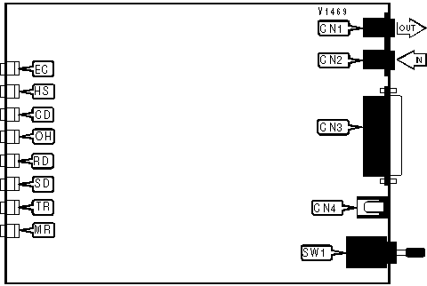
CONNECTIONS | |||
Purpose | Location | Purpose | Location |
Line out | CN1 | DC power | CN4 |
Line in | CN2 | Power switch | SW1 |
RS-232/422 | CN3 | ||
DIAGNOSTIC LED(S) | |||
LED | Color | Status | Condition |
EC | Red | On | Error correction enabled |
EC | Red | Off | Error correction disabled |
HS | Red | On | Modem is operating at highest configured speed |
HS | Red | Off | Modem is operating at less than highest configured speed |
CD | Red | On | Carrier signal detected |
CD | Red | Off | Carrier signal not detected |
OH | Red | On | Modem is off-hook |
OH | Red | Off | Modem is on-hook |
RD | Red | On | Modem is receiving data |
RD | Red | Off | Modem is not receiving data |
SD | Red | On | Modem is transmitting data |
SD | Red | Off | Modem is not transmitting data |
TR | Red | On | DTR signal is high |
TR | Red | Off | DTR signal is low |
MR | Red | On | DSR signal is high |
MR | Red | Off | DSR signal is low |
Proprietary AT Command Set
AT COMMAND RESPONSE | |
Type: | Regtster |
Format: | AT [cmds] S84=n [cmds] |
Example: | AT S84=0 &W <CR> |
Description: | Sets the response to AT commands. |
Command | Function |
| » S84=0 | Normal operation |
S84=1 | Execute valid commands, suppress error codes. |
S84=2 | Ignore configuration commands, always return OK error code. |
AUTO BAUD | |
Type: | Register |
Format: | AT [cmds] S78=n [cmds] |
Example: | AT S78=0 &W <CR> |
Description: | Allows modem to connect at remote modem’s modulation during V.32bis connection. |
Command | Function |
| » S78=0 | Auto baud enabled. |
S78=1 | Auto baud disabled. |
AUTO-RELIABLE TIME BUFFER CONFIGURATION | |
Type: | Configuration |
Format: | AT [cmds] \Cn [cmds] |
Example: | AT \C1 &W <CR> |
Description: | Controls the handling of incoming data during auto-reliable time period. |
Command | Function |
| » \CO | Data is discarded. |
\C1 | Data is buffered. |
\C2 | Data is discarded, resets to \C1 on receipt of autoreliable fallback character. |
AUTO-RELIABLE FALLBACK CHARACTER | |
Type: | Configuration |
Format: | AT [cmds] %An [cmds] |
Example: | AT%A20 <CR> |
Default: | 13 |
Range: | 0-127 |
Unit: | ASCII |
Description: | Sets the character used as the auto-reliable fallback character. %A0 will disable this function. |
BREAK TYPE | |
Type: | Configuration |
Format: | AT [cmds] \Kn [cmds] |
Example: | AT \K5 &W <CR> |
Description: | Selects response to DTE break command. |
Command | Function |
\K0 | Send break, clear buffer, enter command mode. |
\K1 | Send break, clear buffer. |
\K2 | Send break, send data, enter command mode. |
\K3 | Send break. send data. |
\K4 | Send data, send break, enter command mode. |
| » \K5 | Send data, send break. |
CELLULAR ENHANCEMENTS | |
Type: | Register |
Format: | AT [cmds] S91=n [cmds] |
Example: | AT S91=0 &W <CR> |
Description: | Configures modem to enhanced cellular mode |
Command | Function |
| » S91=0 | Disabled |
S91=1 | Enabled |
CD SIGNAL | |
Type: | Configuration |
Format: | AT [cmds] &Cn [cmds] |
Example: | AT &C3 &B0<CR> |
Description: | Configures the behavior of the carrier detect signal. |
Command | Function |
| » &C0 | CD forced high. |
&C1 | CD normal. |
&C2 | Blink on disconnect. |
&C3 | CD follows DTR. |
&C4 | Simulated control carrier. |
&C5 | CD follows DTR, forced low on disconnect. |
COMPRESSION | |
Type: | Configuration |
Format: | AT %Cn |
Example: | AT &B0 %C1 &I2 <CR> |
Description: | Selects V.42 and MNP data compression. |
Command | Function |
%C0 | Data compression disabled. |
| » %C1 | Data compression enabled. |
CONNECT MODE | |
Type: | Configuration |
Format: | AT [cmds] \Nn [cmds] |
Example: | AT \N1 DT555-1212 <CR> |
Description: | Sets connect mode. |
Command | Function |
\N0 | Normal mode enabled. |
\N1 | Direct mode enabled. |
\N2 | MNP mode only enabled. |
\N3 | MNP mode with fallback to normal mode enabled. |
\N4 | LAP-M mode only enabled. |
\N5 | LAP-M mode with fallback to normal mode enabled. |
\N6 | V.42/MNP only enabled. |
| » \N7 | V.42/MNP with fallback to normal mode enabled. |
CONNECTION SPEED UPPER LIMIT | |
Type: | Immediate |
Format: | AT [cmds] %Bn [cmds] |
Example: | AT %B14400 <CR> |
Description: | Selects the current DCE speed. |
Command | Function |
%B300 | Select V.21 or Bell103 at 300bps speed. |
%B1200 | Select V.22,V.23 or Bell 212A at 1200bps speed. |
%B2400 | Select V.22 at 2400bps speed. |
%B4800 | Select v.32/V.32bis at 4800bps speed. |
%B7200 | Select V.32bis at 7200bps speed. |
%B9600 | Select V.32bis/V.32 at 9600bps speed. |
%B12000 | Select V.32bis at 12Kbps speed. |
| » %B14400 | Select V.32bis at 14.4Kbps speed. |
CTS SIGNAL | |
Type: | Configuration |
Format: | AT [cmds] \Dn [cmds] |
Example: | AT \D0 <CR> |
Description: | Selects the function of the CTS signal. |
Command | Function |
| » \D0 | CTS forced high. |
\D1 | CTS normal. |
\D2 | CTS interrupted for 2 seconds on disconnect. |
\D3 | CTS follows DTR. |
DISCONNECT IMMEDIATELY | |
Type: | Configuration |
Format: | AT [cmds] S85=n [cmds] |
Example: | AT S85=0 &W <CR> |
Description: | Disconnect immediately on receipt of disconnect signal from DTE or diagnostic control panel. |
Command | Function |
| » S85=0 | Disabled. |
S85=1 | Enabled. |
FAX DISABLE | |
Type: | Configuration |
Format: | AT [cmds] S79=n [cmds] |
Example: | AT S79=1 &W <CR> |
Description: | Enables V.17 fax capability |
Command | Function |
S79=0 | Disable |
| » S79=1 | Enable |
FLOW CONTROL | |
Type: | Configuration |
Format: | AT [cmds] \Gn [cmds] |
Example: | AT \G1 &K3 <CR> |
Description: | Selects modem port flow control. |
Command | Function |
| » \G0 | Flow control disabled. |
\G1 | Flow control enabled. |
FLOW CONTROL TYPE | |
Type: | Configuration |
Format: | AT [cmds] \Qn [cmds] |
Example: | AT \Q5 <CR> |
Description: | Sets type of flow control used by modem. |
Command | Function |
\Q0 | Flow control disabled. |
\Q1 | Bidirectional XON/XOFF flow control enabled. |
\Q2 | CTS flow control by DCE enabled. |
| » \Q3 | Bidirectional CTS/RTS flow control enabled. |
\Q4 | XON/XOFF flow control by DCE enabled. |
\Q5 | XON/XOFF flow control by DTE enabled. |
\Q6 | RTS flow control by DTE enabled. |
INACTIVITY TIMER | |
Type: | Register |
Format: | AT [cmds] \Tn [cmds] |
Example: | AT\T20 <CR> |
Default: | 0 |
Range: | 0-255 |
Unit: | 1 minute |
Description: | Sets the length of time that the modem does not receive information before it disconnects. |
LAP-M FRAME SIZE | |
Type: | Configuration |
Format: | AT [cmds] \An [cmds] |
Example: | AT \A3 %C1 <CR> |
Description: | Sets the maximum frame size for V.42 and MNP connections. |
Command | Function |
\A0 | Maximum frame size is 64 |
\A1 | Maximum frame size is 128 |
\A2 | Maximum frame size is 192 |
| » \A3 | Maximum frame size is 256 |
\A4 | Maximum frame size is 32 |
\A5 | Maximum frame size is 16 |
Note: Maximum V.42 frame size is 128. | |
LAP-M FRAME WINDOW | |
Type: | Register |
Format: | AT [cmds] S89=n [cmds] |
Example: | ATS89=6 <CR> |
Default: | 0 |
Range: | 1-9 |
Unit: | 1 frame (beginning with 0=6 frames) |
Description: | Sets the number of frames used in V.42 and V.42bis transmissions |
LINE SPEED | |
Type: | Register |
Format: | AT [cmds] S41=n [cmds] |
Example: | ATS41=6 <CR> |
Default: | 1 |
Description: | Sets maximum line speed |
Command | Function |
| » S41=1 | 14.4Kbps V.32bis |
S41=2 | 12.0Kbps V.32bis |
S41=3 | 9600bps V.32bis, V.32 |
S41=4 | 7200bps V.32bis |
S41=5 | 4800bps V.32bis, V.32 |
S41=6 | 2400bps V.22bis |
S41=7 | 1200bps V.22 |
S41=8 | 1200bps 212A |
S41=10 | 0-300bps V21 |
S41=11 | 0-300bps 103j |
S41=12 | 1200/75bps V.23 |
S41=13 | 75/1200bps V.23 |
LOCK SERIAL PORT | |
Type: | Configuration |
Format: | AT [cmds] S90=n [cmds] |
Example: | AT S90=0 <CR> |
Description: | Sets operation of serial port speed. |
Command | Function |
S90=0 | Disabled. |
S90=1 | Serial speed follows connect speed. |
TRANSMISSION LEVEL | |
Type: | Register |
Format: | AT [cmds] &In [cmds] |
Example: | AT &I26 &W <CR> |
Default: | 0 |
Range: | -10dBm to -.25dBm |
Unit: | -1 dBm |
Description: | Sets the signal level for transmission |
TRANSMISSION LEVEL | |
Type: | Configuration |
Format: | AT [cmds] &J0 [cmds] |
Example: | AT &J0 &W <CR> |
Description: | Sets permissive mode |
V.32bis AUTO-RETRAIN | |
Type: | Configuration |
Format: | AT [cmds] S76=n [cmds] |
Example: | AT S76=0 &W <CR> |
Description: | Selects action the modem will take during bad line quality on 32bis connection. |
Command | Function |
| » S76=0 | Auto retrain enabled. |
S76=1 | Auto retrain disabled. |
| S76=2 | Auto retrain started at 4800bps. |
S76=3 | Auto retrain started at 9600bps |
V.32bis TRAIN | |
Type: | Register |
Format: | AT [cmds] S43=n [cmds] |
Example: | AT S43=0 &W <CR> |
Description: | Sets train length. Cellular setting is short. |
Command | Function |
| » S43=0 | Long |
S43=1 | Short |
XON/XOFF PASS-THROUGH | |
Type: | Configuration |
Format: | AT [cmds] \Xn [cmds] |
Example: | AT \X7 O <CR> |
Description: | Selects whether XON/XOFF signals are sent to remote modem. |
Command | Function |
| » \X0 | XON/XOFF signals trapped by local modem. |
\X1 | XON/XOFF passed through local modem. |
My Books

