DATASMART T3/E3 SMDSU MODEL 1596X (AC POWER) modem/telephone/ISDN Settings and Configuration
ADC KENTROX
DATASMART T3/E3 SMDSU MODEL 1596X (AC POWER)
Card Type | T3/E3 CSU/DSU |
Chipset | Unidentified |
T3/E3 Transfer Rate | 34.368Mbps (E3) 44.736Mbps (T3) |
T3/E3 Protocol | M13, C-Bit, G.751, B8ZS |
Frame Type | Unidentified |
Data Bus | Serial |
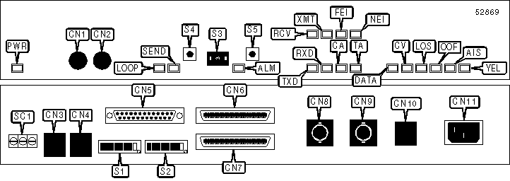
CONNECTIONS | |||
Function | Label | Function | Label |
Monitor jack | CN1 | T3/E3 line in/out | CN8 |
Monitor jack | CN2 | T3/E3 line in/out | CN9 |
DCE serial control port | CN3 | RS-422 auxiliary clock port | CN10 |
DTE serial control port | CN4 | AC power in | CN11 |
V.35 serial data port via DB-25 connector | CN5 | Alarm relay (see pinout below) | SC1 |
HSSI serial data port | CN6 | Alarm cutoff switch | S5 |
HSSI serial data port | CN7 | ||
Note:Standard V.35 serial port is provided on an included adapter cable. | |||
SC1 PINOUT | |||
Function | Screw | Function | Screw |
Normally closed contact | 1 | Normally open contact | 3 |
Signal common | 2 | ||
USER CONFIGURABLE SETTINGS | |||
Setting | Label | Position | |
| » | Control port parity disabled | S1/3 | On |
Control port parity enabled | S1/3 | Off | |
| » | Control port parity set to odd | S1/4 | On |
Control port parity set to even | S1/4 | Off | |
| » | Control port uses 8 data bits | S1/5 | On |
Control port uses 7 data bits | S1/5 | Off | |
| » | Control port uses 1 stop bit | S1/6 | On |
Control port uses 2 stop bits | S1/6 | Off | |
| » | Alarm reporting disabled | S1/7 | On |
Alarm reporting enabled | S1/7 | Off | |
| » | Alarm reporting output to DCE control port | S1/8 | On |
Alarm reporting output to DTE control port | S1/8 | Off | |
| » | Adapter in SMDS mode | S2/3 | On |
Adapter in DSU mode | S2/3 | Off | |
| » | T3/E3 receive equalization enabled | S2/4 | On |
T3/E3 receive equalization disabled | S2/4 | Off | |
| » | T3/E3 transmit Line Build Out out | S2/5 | On |
T3/E3 transmit Line Build Out in | S2/5 | Off | |
| » | Factory configured - do not alter | S2/6 | On |
| » | Factory configured - do not alter | S2/7 | On |
| » | Factory configured - do not alter | S2/8 | On |
CONTROL PORT SPEED SELECTION | |||
Setting | S1/1 | S1/2 | |
| » | 9600bps | On | On |
4800bps | On | Off | |
2400bps | Off | On | |
1200bps | Off | Off | |
PROTOCOL SELECTION | |||
Setting | S2/1 | S2/2 | |
| » | T3 MI3 | On | On |
T3 C-Bit | On | Off | |
E3 G.751 | Off | On | |
E3 G.751 | Off | Off | |
THUMBWEEL FUNCTION SELECTION | |||
Function | S3 | S4 | S5 |
Reset loopback tests | Pushed | Position 0 | Not pushed |
Begin remote line loopback test | Pushed | Position 1 | Not pushed |
Begin remote payload loopback test | Pushed | Position 2 | Not pushed |
Reset to factory defaults and switch settings | Pushed for 2 sec. | Position 3 | Pushed for 2 sec. |
Begin near-end line loopback test | Pushed | Position 4 | Not pushed |
Begin near-end payload loopback test | Pushed | Position 5 | Not pushed |
Begin near-end local loopback test | Pushed | Position 6 | Not pushed |
Begin data near-end terminal loopback test | Pushed | Position 7 | Not pushed |
Reset SMDSU address to 00:00:000 | Pushed for 2 sec. | Position 7 | Pushed for 2 sec. |
Note:S3 and S5 must always be held for at least one-half of one second for the above functions to take effect. | |||
DIAGNOSTIC LED(S) | |||
LED | Color | Status | Condition |
PWR | Green | On | Power is on |
PWR | Red | On | Self-test failed |
PWR | N/A | Off | Power is off |
LOOP | Yellow | On | Local loopback test in progress |
LOOP | Yellow | Blinking | Remote loopback test in progress |
LOOP | Yellow | Off | Loopback test not in progress |
SEND | Yellow | On | Test code being sent |
SEND | Yellow | Blinking | Remote loopback test may be in progress but cannot be verified |
SEND | Yellow | Off | Test code not being sent |
ALM | Red | On | Alarm condition detected and awaiting user intervention |
ALM | Green | On | Alarm condition detected; user intervention in progress |
ALM | N/A | Off | Alarm condition not detected |
RCV | Green | On | DSU is receiving data from network |
RCV | Green | Off | DSU is not receiving data from network |
XMT | Green | On | DSU is transmitting data to network |
XMT | Green | Off | DSU is not transmitting data to network |
FEI | Red | On | Remote is out of PLCP lock |
FEI | Red | Blinking | Remote PLCP Code Violation detected |
FEI | Red | Off | Remote PLCP normal |
NEI | Red | On | Local DSU is out of PLCP lock |
NEI | Red | Blinking | Local DSU PLCP Code Violation detected |
NEI | Red | Off | Local DSU PLCP normal |
TXD | Yellow | On | Control port is transmitting data |
TXD | Yellow | Off | Control port is not transmitting data |
DIAGNOSTIC LED(S) (CON’T) | |||
LED | Color | Status | Condition |
RXD | Yellow | On | Control port is receiving data |
RXD | Yellow | Off | Control port is not receiving data |
TA | Yellow | On | V.24 DTR or V.35 TA signal is high |
TA | Yellow | Off | V.24 DTR or V.35 TA signal is low |
CA | Yellow | On | V.24 DCD or V.35 CA signal is high |
CA | Yellow | Off | V.24 DCD or V.35 CA signal is low |
DATA | Green | On | Valid data signal detected |
DATA | Green | Off | No valid signal detected |
CV | Red | On | Code Violation error detected |
CV | Red | Off | Code Violation error not detected |
LOS | Red | On | Loss Of Signal condition detected |
LOS | Red | Off | Loss Of Signal condition not detected |
OOF | Red | On | Signal is out of frame synchronization |
OOF | Red | Off | Signal is not out of frame synchronization |
AIS | Red | On | Alarm Indication Signal condition detected |
AIS | Red | Off | Alarm Indication Signal condition not detected |
YEL | Yellow | On | Remote Yellow Alarm condition detected |
YEL | Yellow | Blinking | Local Yellow Alarm condition detected |
YEL | Yellow | Off | Yellow Alarm condition not detected |
My Books

