UN-451 IO card Settings and Configuration
MICRO EQUIPMENT CORPORATION
UN-451
Card Type | Multi I/O card |
Chipset/Controller | Unknown |
I/O Options | Game port, parallel port, serial ports (2) |
Maximum DRAM | N/A |
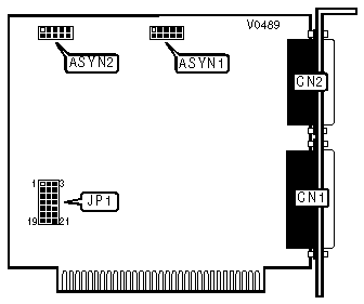
CONNECTIONS | |||
Purpose | Location | Purpose | Location |
Parallel port | CN1 | Serial port 1 | ASYN1 |
Game port | CN2 | Serial port 2 (optional) | ASYN2 |
PARALLEL PORT CONFIGURATION | ||
LPT/Address/IRQ | JP1 | |
| » | LPT1/378h/IRQ7 | Pins 5 & 6/2 & 3 closed |
LPT2/278h/IRQ5 | Pins 4 & 5/1 & 2 closed | |
Disable | Pins 4, 5, & 6/1, 2, & 3 all open | |
SERIAL PORT 1 (ASYN1) CONFIGURATION | ||
COM/Address/IRQ | JP1 | |
| » | COM1/3F8h/IRQ4 | Pins 20 & 21/10 & 11 closed |
COM2/2F8h/IRQ3 | Pins 16 & 17/11 & 12 closed | |
COM4/2E8h/IRQ3 | Pins 19 & 20/11 & 12 closed | |
Disable | Pins 16 & 17/19, 20, & 21/10, 11, & 12 all open | |
SERIAL PORT 2 (ASYN2) CONFIGURATION | ||
COM/Address/IRQ | JP1 | |
| » | COM2/2F8h/IRQ3 | Pins 17 & 18/8 & 9 closed |
COM3/3E8h/IRQ4 | Pins 13 & 14/7 & 8 closed | |
COM4/2E8h/IRQ3 | Pins 14 & 15/8 & 9 closed | |
Disable | Pins 17 & 18/13, 14, & 15/7, 8, & 9 all open | |
MISCELLANEOUS TECHNICAL NOTES |
Serial port 2 (ASYN2) exists only on model UN451b. Model UN-451a has only one serial port |
The pin numbers for JP1 printed on the actual card are incorrect. Use the numbers depicted on the above diagram to re-configure the card. |
The game port can be disabled by cutting a wire on the soldering side of the card. It is located near the edge opposite of the external ports and toward the center. |
My Books

