LPC SERIAL/2A IO card Settings and Configuration
COMPUTER MODULES, INC.
LPC SERIAL/2A
Card Type | Serial |
Chip Set | Zilog |
I/O Options | Serial ports (2) |
Data Bus | 8-bit ISA |
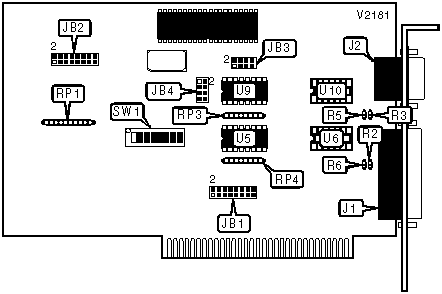
CONNECTIONS | |||
Function | Label | Function | Label |
Serial port 1 (May be RS-232, RS-422/423, or RS-485) | J1 | Serial port 2 (RS-232 only) | J2 |
USER CONFIGURABLE SETTINGS | |||
Setting | Label | Position | |
| » | Factory configured - do not alter | SW1/1 | Off |
CLOCK SOURCE FOR PORT 1 | |
Setting | JB3 |
External clock from serial RTxC | Pins 1 & 2 closed |
Internal clock from 8254 | Pins 1 & 3, 2 & 4 closed |
DMA CHANNEL - RECEIVE | |
Setting | JB1 |
DMA1 | Pins 9 & 10, 13 & 14 closed |
DMA3 | Pins 10 & 12, 14 & 16 closed |
Disabled | Above pins open |
DMA CHANNEL - TRANSMIT | |
Setting | JB1 |
DMA1 | Pins 9 & 11, 13 & 15 closed |
DMA3 | Pins 11 & 12, 15 & 16 closed |
Disabled | Above pins open |
Note: If a DMA is used for transmission then port 1 may not be used. | |
BASE I/O ADDRESS | ||||||||
Setting | SW1/2 | SW1/3 | SW1/4 | SW1/5 | SW1/6 | SW1/7 | SW1/8 | |
000h | On | On | On | On | On | On | On | |
008h | On | On | On | On | On | On | Off | |
010h | On | On | On | On | On | Off | On | |
018h | On | On | On | On | On | Off | Off | |
020h | On | On | On | On | Off | On | On | |
| » | 380h | Off | Off | Off | On | On | On | On |
3D8h | Off | Off | Off | Off | On | Off | Off | |
3E0h | Off | Off | Off | Off | Off | On | On | |
3E8h | Off | Off | Off | Off | Off | On | Off | |
3F0h | Off | Off | Off | Off | Off | Off | On | |
3F8h | Off | Off | Off | Off | Off | Off | Off | |
Note: A total of 127 base address settings are available. The switches are a binary representation of the decimal memory addresses. SW1/2 is the Most Significant Bit and switch SW1/8 is the Least Significant Bit. The switches have the following decimal values: SW1/8=8, SW1/7=16, SW1/6=32, SW1/5=64, SW1/4=128, SW1/3=256, SW1/2=512. Turn off the switches and add the values of the switches that are off to obtain the correct memory address. (Off=1, On=0) | ||||||||
INTERRUPT | |
Setting | JB1 |
IRQ3 internally | Pins 1 & 2 closed |
IRQ3 from 8254 | Pins 1 & 3 closed |
IRQ4 internally | Pins 2 & 4 closed |
IRQ4 from 8254 | Pins 3 & 4 closed |
IRQ5 internally | Pins 5 & 6 closed |
IRQ5 from 8254 | Pins 5 & 7 closed |
IRQ7 internally | Pins 6 & 8 closed |
IRQ7 from 8254 | Pins 7 & 8 closed |
PORT 1 TYPE | |||||
Setting | JB4 | U5 | U6 | U9 | U10 |
RS-232 | Pins 1 & 2, 4 & 5 open | Not installed | MC1489 | Not installed | MC1488 |
RS-422/423 | Pins 1 & 2, 4 & 5 open | 26LS32 | Not installed | 26LS31 | Not installed |
RS-485 | Pins 1 & 2, 4 & 5 closed | 26LS32 | Not installed | 26LS31 | Not installed |
PORT 1 PINS 9 & 10 | |
Setting | JB3 |
+12V DC | Pins 7 & 8 closed |
Not used | Pins 7 & 8 open |
PORT 1 RS-422/423/485 DRIVER | |
Setting | JB3 |
Enabled by RTS | Pins 5 & 6 closed |
Enabled permanently | Pins 3 & 5 closed |
PORT 1 RS-422/423 DRIVER TERMINATION | |||
Setting | JB4 | RP3 | RP4 |
Not terminated | Pins 5 & 6, 7 & 8 closed | Not installed | Not installed |
Terminated | Pins 5 & 7, 6 & 8 closed | Installed | Installed |
Note: The ohm values of RP3 and RP4 should be determined to cause a difference in voltage of at least 2.0V between the ends of the serial cable. | |||
8254 CLK0 SOURCE | |
Setting | JB2 |
8254 clock signal | Pins 15 & 16 closed |
Disabled | Pins 15 & 16 open |
8254 CLK1 SOURCE | |
Setting | JB2 |
8254 clock signal | Pins 13 & 14 closed |
8254 CLK0 | Pins 11 & 13 closed |
Disabled | Above pins open |
8254 CLK2 SOURCE | |
Setting | JB2 |
8254 clock signal | Pins 10 & 12 closed |
8254 CLK1 | Pins 9 & 10 closed |
Disabled | Above pins open |
CLK0 INTERRUPT GENERATOR | |
Setting | JB2 |
CLK0 generates interrupt | Pins 7 & 8 closed |
CLK0 does not generate interrupt | Pins 7 & 8 open |
CLK1 INTERRUPT GENERATOR | |
Setting | JB2 |
CLK1 generates interrupt | Pins 5 & 6 closed |
CLK1 does not generate interrupt | Pins 4 & 6 open |
CLK2 INTERRUPT GENERATOR | |
Setting | JB2 |
CLK2 generates interrupt | Pins 1 & 3 closed |
CLK2 does not generate interrupt | Pins 1 & 2 open |
MISCELLANEOUS TECHNICAL NOTE |
When using RS-422, resistors R2, R3, R5, and R6 must be installed to match the impedance of the cable that is used. The board will not function properly in RS-422 mode without these resistors. |
My Books

