1060 modem/telephone/ISDN Settings and Configuration
PATTON ELECTRONICS COMPANY
1060
Card Type | Modem |
Chip Set | Unidentified |
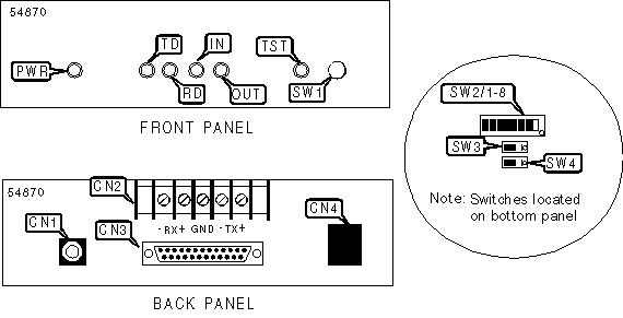
I/O Options | Power connector, 25-pin connector, terminal block network interface via RJ-11 connector |
Wiring Type | RJ-11 shielded twisted pair |
Topology | Daisy chain, star |
Maximum Data Rate | 115.2Kbps |
Data Bus | External |
CONNECTIONS | ||||||
Function | Label | Function | Label | |||
Power connector | CN1 | Network interface via RJ-11 connector | CN4 | |||
Terminal block | CN2 | Loopback test switch | SW1 | |||
DTE/DCE serial port (25-pin connector) | CN3 | |||||
USER CONFIGURABLE SETTINGS | ||
Setting | Label | Position |
í Factory configured - do not alter | SW1/8 | Unidentified |
DTE/DCE | ||
Function | SW3 | SW4 |
DTE (modem or multiplexer) | On | On |
DCE (PC, terminal or host) | Off | Off |
DCE MODE PARAMETERS | ||||||||||||||||||||||||||||
Control in | Control out | Voltage out | Carrier Control | SW1/1 | SW1/2 | SW1/3 | SW1/4 | SW1/5 | SW1/6 | SW1/7 | ||||||||||||||||||
4 | 8 | 6 | Disabled | On | On | On | Off | Off | Off | Off | ||||||||||||||||||
4 | 8 | 6 | Enabled | On | On | On | Off | Off | Off | On | ||||||||||||||||||
4, 11, 20 | 8 | 6 | Disabled | Off | On | On | On | Off | Off | Off | ||||||||||||||||||
4, 11, 20 | 8 | 6 | Enabled | Off | On | On | On | Off | Off | On | ||||||||||||||||||
4 | 6 | 8 | Disabled | On | Off | Off | Off | On | On | Off | ||||||||||||||||||
4 | 6 | 8 | Enabled | On | Off | Off | Off | On | On | On | ||||||||||||||||||
4, 11, 20 | 6 | 8 | Disabled | Off | Off | Off | On | On | On | Off | ||||||||||||||||||
4, 11, 20 | 6 | 8 | Enabled | Off | Off | Off | On | On | On | On | ||||||||||||||||||
Note: | Multiple input pins are "or-tied." If input goes low, carrier is dropped. Multiple output pins generate the same signal simultaneously | |||||||||||||||||||||||||||
DTE MODE PARAMETERS | ||||||||||||||||||||||||||||||
Control in | Control out | Voltage out | Carrier Control | SW1/1 | SW1/2 | SW1/3 | SW1/4 | SW1/5 | SW1/6 | SW1/7 | ||||||||||||||||||||
8 | 4 | 11, 20 | Disabled | On | On | On | Off | Off | Off | Off | ||||||||||||||||||||
8 | 4 | 11, 20 | Enabled | On | On | On | Off | Off | Off | On | ||||||||||||||||||||
5, 6, 8 | 4 | 11, 20 | Disabled | Off | On | On | On | Off | Off | Off | ||||||||||||||||||||
5, 6, 8 | 4 | 11, 20 | Enabled | Off | On | On | On | Off | Off | On | ||||||||||||||||||||
8 | 11, 20 | 4 | Disabled | On | Off | Off | Off | On | On | Off | ||||||||||||||||||||
8 | 11, 20 | 4 | Enabled | On | Off | Off | Off | On | On | On | ||||||||||||||||||||
5, 6, 8 | 11, 20 | 4 | Disabled | Off | Off | Off | On | On | On | Off | ||||||||||||||||||||
5, 6, 8 | 11, 20 | 4 | Enabled | Off | Off | Off | On | On | On | On | ||||||||||||||||||||
Note: | Multiple input pins are "or-tied." If input goes low, carrier is dropped. Multiple output pins generate the same signal simultaneously | |||||||||||||||||||||||||||||
MULTIPOINT TOPOLOGY | |||||||||||||||||||
Setting | SW1/1 | SW1/2 | SW1/3 | SW1/4 | SW1/5 | SW1/6 | SW1/7 | ||||||||||||
Master positions | On | On | On | Off | Off | Off | Off | ||||||||||||
Slave positions | On | On | On | Off | Off | Off | On | ||||||||||||
Note: These settings are used when the device is daisy-chained | |||||||||||||||||||
DIAGNOSTIC LED(S) | |||
LED | Color | Status | Condition |
PWR | Green | On | Power is on |
PWR | Green | Off | Power is off |
TD | Red | On | Low RS-232 logic level |
TD | Red/Green | Blinking | Data is being transmitted (high logic level) |
TD | None | Off | Data is not being transmitted |
RD | Red | On | Low RS-232 logic level |
RD | Red/Green | Blinking | Data is being received (high logic level) |
RD | None | Off | Data is not being received |
IN | Red | On | Low signal detected on control input (pins vary according to switch selection) |
IN | Green | On | High signal detected on control input pins |
IN | None | Off | No signal being detected on control input pins |
OUT | Red | On | Low signal detected on control output (pins vary according to switch selection) |
OUT | Green | On | High signal detected on control output pins |
OUT | None | Off | No signal being detected on control input pins |
TST | Red | On | Device is conducting LAL, or RAL test (depress switch to run test) |
TST | Red | Off | Device is not conducting a test |
My Books

