DAC960P, DAC960PD, DAC960PD-ULTRA Hard Disk/Floppy Controller Settings and Configuration
MYLEX CORPORATION
DAC960P, DAC960PD, DAC960PD-ULTRA
Processor | RISC |
Maximum Onboard Memory | 4/8/16/32MB (n x 36) optional DRAM 4/8MB (n x 36) optional EDRAM |
Data Bus | 32-bit PCI |
Card Size | Full-length, full-height card |
Hard Drives supported | Up to 45 Ultra-SCSI devices (DAC960PD-Ultra) Up to 45 Fast SCSI-2/Wide SCSI devices (DAC960P/PD) |
Floppy Drives supported | None |
RAID Levels supported | 0,1,5, and 0+1 |
CONNECTIONS | |||
Function | Location | Function | Location |
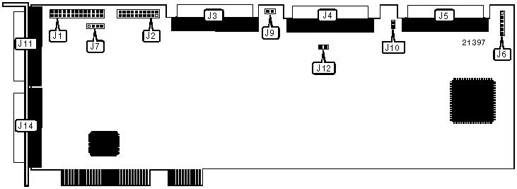
26-pin connector - AEMI port | J1 | 68-pin SCSI connector - channel 2 internal | J5 |
10-pin connector - battery backup (optional) | J2 | 6-pin connector - bus/drive active LED | J6 |
68-pin SCSI connector - channel 0 internal | J3 | 68-pin SCSI connector - channel 0 external | J11 |
68-pin SCSI connector - channel 1 internal | J4 | 68-pin SCSI connector - channel 1 external | J14 |
Note: AEMI is the acronym for Array Enclosure Management Interface. | |||
USER CONFIGURABLE SETTINGS | ||||
Function | Label | Position | ||
| » | Factory configured - do not alter | J7 | Unidentified | |
| » | SCSI channel 0 termination enabled | J9 | Closed | |
SCSI channel 0 termination disabled | J9 | Open | ||
| » | SCSI channel 2 termination enabled | J10 | Closed | |
SCSI channel 2 termination disabled | J10 | Open | ||
| » | SCSI channel 1 termination enabled | J12 | Closed | |
SCSI channel 1 termination disabled | J12 | Open | ||
Enable termination on a SCSI channel if the controller is installed at one end of the channel. This setting terminates the channel and powers the SCSI TERMPWR signal. Disable termination on a SCSI channel if the controller is not at the end of the channel (i.e., both external and internal devices exist on the same channel). | ||||
DIAGNOSTIC LED(S) | ||
LED | Status | Condition |
J6/pins 1 & 2 | On | SCSI is active (Data is being transmitted/received across SCSI channels) |
J6/pins 1 & 2 | Off | No SCSI activity |
J6/pins 3 & 4 | On | PCI is active (Data is being transmitted/received to/from host) |
J6/pins 3 & 4 | Off | No PCI activity |
J6/pins 5 & 6 | On | Write is pending (Cache holds data that needs to be written to disk) |
J6/pins 5 & 6 | Off | No write is pending |
Note: If the system loses power or is reset while J6/pins 5 & 6 are on, the data in cache memory will be lost. Installing optional cache battery backup module J2 will avoid data loss. | ||
My Books

